


 |

|

|

|
|
 |
 |
|||

April, 1926
SINKING IN DURHAM BY THE FREEZING PROCESS
A Brief Account is given by J. L. Henrard, I.E.T.Lg., of the Freezing Equipment, and the Operations Incidental to Freezing the Strata, for the New Shafts being Sunk by The Londonderry Collieries Limited, at Seaham.
Readers of Colliery Engineering will already be familiar with the new sinkings which have been undertaken by The Londonderry Collieries Limited, from the account which appeared of the boring operations, in the June issue of 1925. It will be recalled that two shafts, known as the New Winnings, are being sunk about 350 yards from the shore line, a little to the north of Seaham Harbour. The freezing process is essential to reach the coal measures in this portion of the Durham Coalfield, as the overlying Permian rocks are very permeable, experience gained in sinkings having shown it to be impracticable to rely on direct pumping to penetrate this ground.
The freezing process, as such, is sufficiently well known to make a lengthy description unnecessary here, so that the principle only will be outlined in a few words. This consists essentially of the formation, in the permeable strata, of a large cylinder of frozen ground, in the centre of which it is possible to sink a shaft, this being maintained in a perfectly dry condition due to the protection of the surrounding ice wall. The freezing is accomplished by boring a ring of holes through the permeable strata, slightly outside the site of the shaft, and by circulating through these holes a solution of cold brine, which slowly absorbs the heat from the ground and progressively lowers its temperature to freezing point. Eventually, of course. a temperature considerably below freezing point is reached in order to obtain an ice wall of sufficient thickness and strength to resist the pressure of the water in the strata.
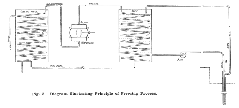
The manner by which the actual freezing is accomplished will be quickly understood by referring to Fig. 3, which shows a diagrammatic arrangement of the equipment employed. In each boring is inserted a length of steel pipe called a freezing tube, which is securely closed at the base. Down this freezing tube is lowered a second length of piping, having a much smaller diameter, open at the end and reaching nearly to the sealed end of the larger tube. These two tubes, as will be seen from the diagram, constitute a freezing circuit. The cold solution of brine enters the boring by way of the smaller tube A and after travelling to the bottom returns in the annular space between the two tubes. In ascending there is a transfer of heat from the ground to the brine, the temperature of the two being exchanged as it were. On reaching the surface the brine is cooled down to its initial temperature again by coming into contact with the coils E of the evaporator. In these evaporators, use is made of the latent heat of evaporisation of a liquid, usually NH3 or CO2, which vaporises at the low temperature at which it is worked.
The vaporisation of the refrigerating agent which is in the coils is produced by a gas pump, which eventually compresses the gas into a condenser C, where, under the influence of the cooling water, it liquefies, only to be expanded into a gas again, in the coils E of the evaporator. These two distinct circuits are maintained for a greater or lesser period according to the nature of the ground, the amount of water which the ground contains, the depth of the shaft, the hydrostatic pressure, &c.
Progress of Work.
There are three distinct stages in shaft sinking by the freezing process — the drilling and lining of the boreholes, the formation and maintenance of the ice column, and the actual sinking operations. It will be as well perhaps to outline the progress which has been made up to the present.The borings have been executed successively at the two shafts. The first one, the "Tempest Shaft," was commenced on October 1, 1924. The last boring of the second shaft, the "Vane Shaft," was completed on February 15, 1926. The borings were drilled three at a time. At the Tempest shaft there are 34 boreholes, which include the test boring and one in the centre for observation purposes, while at the Vane shaft there are 33 holes, including the centre boring. All the holes are drilled to a depth of 535 ft., except those at the centre, which only go as far as the sand.
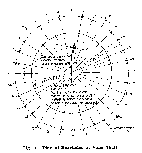
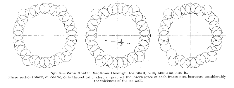
It will be obvious that an important requirement of boreholes sunk for freezing purposes is that they should be vertical, or as vertical as possible. Fig. 4 shows the position and deviation of the Vane Shaft boreholes, which may be regarded as being practically vertical. Fig. 5 gives sections through the ice wall of this shaft at various depths from the surface. Freezing operations were commenced at the Tempest Shaft on September 18, 1925, and the ice wall was completed on January 21, 1926, as. is shown in Fig. 4 by alterations of the water level in the centre boring. The actual sinking operations were begun at this shaft on February 15, 1926. Freezing of the Vane Shaft is now in progress.
The whole undertaking is being executed jointly by the Trefor Boring & Sinking Company of London, and the Société de Fonçage de Puits Franco-Belge of Brussels, both of these companies being specialists in shaft sinking by any process. In this instance the boring was undertaken by the former company, the latter being responsible for the freezing and sinking. They take upon themselves the full responsibility of the ultimate success of the scheme, the price of the contract being a fixed one.
Conditions at Seaham Harbour.
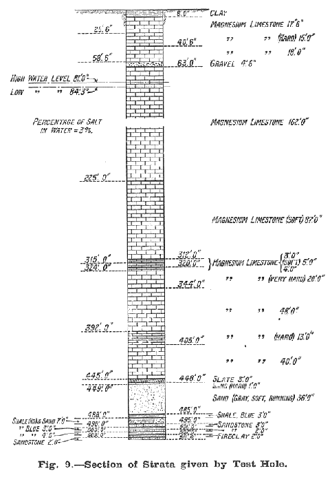
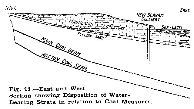
Fig. 11 shows the disposition of the strata in this portion of Durham and indicates the position of the new sinkings in relation to the sea. From the preliminary test hole which was bored in 1922 it was established that the permeable strata gave a section as shown in Fig. 9. The Magnesium Limestone is heavily fissured and contains large gullets which communicate with the sea, while the well known Yellow Sands is a soft, porous, wind-blown formation composed of "millet seed" grains. Communication with the sea is proved by the rise and fall of the water observed in the boring, this movement following the ebb and flow of the tide within a few hours. The difference between high and low water level varied between three and four feet. It was ascertained, too, that the water in the borehole was salty. It can also be observed, that by its special situation near to the sea, the strata which has to be frozen receives water, which naturally flows from inland to the sea. This movement of water, which presents difficulties, makes the freezing of these shafts particularly interesting to follow, as there arises from these, new heat which has to be dealt with. There is no doubt that such a moving mass of water presents great difficulties for freezing. The fact that the water is salty complicates the problem as well.
Drawings and Photographs accompanying the article


Article reproduced from a copy of the magazine held at National Mining Museum Scotland, Newtongrange, Midlothian.




 Contains public sector information licensed under the

