


 |

|

|

|
|
 |
 |
|||

June, 1925
A DURHAM SINKING
The Boring Work Preliminary to Shaft Sinking by the Freezing Process is described in connection with a New Undertaking of Londonderry Collieries Limited.
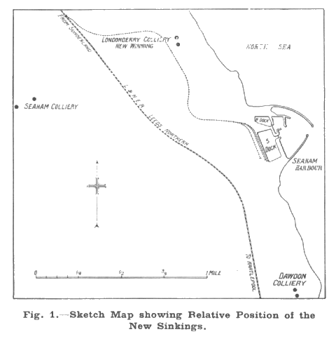
The difficulties of penetrating the Permian strata which covers the south-eastern portion of the Durham coalfield have almost created a legend in the annals of shaft sinking achievement. For instance, Haswell, Horden, Murton, Ryhope were sunk under great difficulties by the open pit pumping process ; at Marsden Colliery insurmountable difficulties were encountered when this method was attempted, and the shafts were finally sunk by the Kind-Chaudron system. An attempt to sink the Dawdon Colliery shafts by ordinary methods was abandoned when they had attained a depth of about 200 ft. and when a total of 7,050 gallons of water per minute had to be pumped; eventually a freezing process was adopted. In the past, sinking in this area has been a speculation which only the boldest were prepared to undertake, since it was mainly a question of luck whether the cost might fall within a reasonable estimate or rise to a figure approaching twice this amount. Modern scientific methods have reduced the hazards to a negligible minimum, and although sinkings under conditions of this kind are naturally accomplished only at an enormous expense, they are now entirely free from that element of uncertainty which makes it an open question whether the difficulties demand a capital expenditure in excess of that on which the profits of exploitation would represent a reasonable dividend. Naturally, it is desirable to have as great a measure of security as is possible in a commercial venture of this magnitude, so that the extra time incurred and the heavy monetary expenditure necessary to penetrate this difficult Permian strata is thus an insurance as well, perhaps, as a technical and economic necessity. In speaking of the venture on the occasion of the annual dinner of the Coal Trade Benevolent Association, Lord Londonderry said that the total cost would be over £1,000,000 and that no return could be expected on this capital for quite five years. He also added that the enterprise would contribute a million tons per annum to the national coal output and would provide employment for 3,000 or more men for at least 100 years. It is a magnificent project, and we wish the company every success that such a scheme should be launched in a time of such political uncertainty surely savours more of altruism than any of the labour champions would care to admit. It is to Mr. W. A. Swallow, the manager of Seaham Colliery, who also has the new undertaking in hand, to whom we are indebted for facilities to visit the sinkings and to publish this article. We much appreciate the assistance he was good enough to give us.
The Strata.
The Permian rocks of south-east Durham are much too well known to require other than a very brief mention here. They consist of the heavily fissured Magnesian Limestone, Marl Slates, and the porous Yellow Sands. The last mentioned, which immediately overlies the coal measures, is a softish sandstone ; its irregular thickness, intense false bedding and rounded, "millet-seed" grains suggesting that it is a wind-blown formation. The overlying Magnesian Limestone is obviously of marine origin, and there is evidence to prove that it was deposited in an inland sea which was gradually drying up. It contains numerous fissures and fractures, much of the fracturing, according to the late D. Wollacott, D.Sc. — an unassailable authority on the geology of this coalfield — following more or less horizontal planes. Previous sinkings have proved both these strata to contain excessive feeders of water, the gullets in the limestone frequently carrying brine from the sea.
The following table gives the chief underlying coal seams, their depth from the surface, and their thickness :—
| Seam. | Depth from the surface. | Thickness. | |
| Main coal | 278 | fths. | 4 ft. 6 in-5 ft. |
| Maudlin | 287 | ,, | 4 ft. 6 in. |
| Hutton | 309 | ,, | 3 ft. 10 in. |
| Harvey | 336 | ,, | 2 ft. 7 in. |
| Busty | 350 | ,, | 2ft. 6in. |
The site for the new shafts is about 350 yards from the high-water mark, and some 70 feet above this datum. Both the Hutton and Maudlin seams have been previously worked underneath, and the coal has been obtained as far as three-quarters of a mile from the shore line. Many of the working places were stopped, however, as long ago as 1892 and operations in the remainder, in the Maudlin seam, were discontinued during the war. Working the more advanced faces entailed the coal being brought to the Seaham Colliery shafts, a total distance of about three miles, scarcely an economic proposition with an extensive royalty yet to win. The new shafts have thus been sunk with the object of exploiting the north-eastern portion of the Company's royalty, which is at present too remote from the existing accesses.
Sinking Preliminaries.
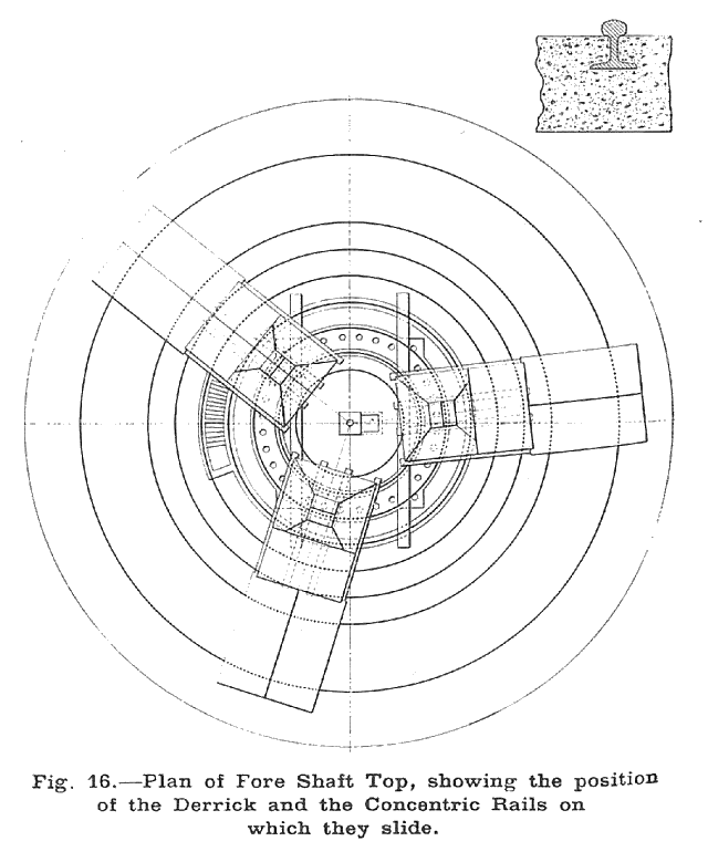
Two shafts having centres 66 2/3 yards apart are to be sunk each having a finished diameter of 21 ft. A preliminary borehole was drilled to prove the strata, and it was found that the Yellow Sands commenced at a depth of 445 ft. from the surface and was 40 ft. in thickness. From the outset it had been decided to adopt a freezing process, and the contract was secured by the Trefor Poring and Sinking Company, London, and the Société Franco-Belge de Fonçage, of Brussels, who are operating jointly, accepting between them the full responsibility for the ultimate success of the scheme. It was at first intended to carry the freezing process to some 35 ft. into the coal measures, but the weathering effect due to contact with the water in the sands had disintegrated the upper 25 ft., so that it was necessary to proceed with the bore-holes to a depth of 535 ft. The sound coal measures are thus penetrated to a depth of 25 ft., this being sufficient to guard against any possibility of water percolating through from the water-bearing strata above. Operations are at present confined solely to putting down the bore-holes and erecting the necessary machinery for freezing the strata. The first sod was dug by the Viscount Castlereagh on December 19, 1923, and the boring was started on October 27, 1924. since when 25 of the bore-holes surrounding the north or Vane shaft have been finished, lined, and the freezing tubes inserted. Each shaft requires a complement of 32 boreholes drilled at regular intervals around an outer circle of 30 ft. diam., and one in the centre to afford a means of getting information regarding the condition of the strata during freezing their general disposition is shown in Fig. 16. Three holes are drilled at a time, and it is anticipated that the Vane (No. 2) shaft bore-holes will be completed and ready for the freezing operations by the end of July. Freezing the strata will occupy a period of about four months, and in the meanwhile the boring equipment will be moved to the No. 1, or Tempest shaft.
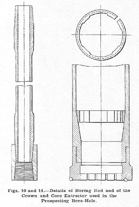
The preliminary bore-hole which was put down to test the strata was, of course, drilled by a diamond-core machine, and it is interesting to note that this hole also has been lined and furnished with a freezing rube to take its part in the freezing of the ice wall it was thus drilled in a pre-arranged position in the 30-ft. circle of bore-holes, with the object of serving in this double capacity, It was started in August, 1923, and for cheapness and quickness the first 200 ft. was drilled with a chisel from this point to the bottom a diamond-core drill was used, and about 80 per cent, of the cores were recovered. Cores 6 in. in diameter were obtained until the sand was reached, when a smaller crown giving a 5-in, core was used. Careful tests were made in this hole to ascertain the permanent water level, and it was found to vary with the tide At high tide the level was 81 ft. below the surface, and 84 ft. when the tide was low. Samples of the water were analysed and were found to be salt. Obviously, these facts complicated the sinkings, since it was evident that the gullies in the limestone were in more or less direct communication with the sea. The difference in level between high and low-water marks at the shore at this point is 11 ft.
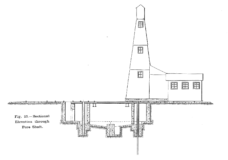
Fig. 15, which gives a diagrammatic section through the entire headworks, shows in an admirable manner the preparatory work which was done prior to the commencement of the actual boring operation, and in addition gives an excellent idea of the general disposition of the boring plant. It will be seen that a short portion of the shaft has been excavated and lined, and that the bottom has been sealed with a bed of concrete. This slopes towards the centre, where a sump has been made to collect the water which normally issues from the bore-holes during the drilling operations. We say "normally," because in this instance very little of the water injected down the boring rods ever returns to the surface, but finds its way to the sea through the numerous gullies in the limestone. Ordinarily, however, the returned water is pumped from the central sump into settling tanks, and when the sediment has thus been removed the water is used over again.
Attention is called to the built-up 2 ft. by 20 in. steel girders, which are, of course, in their permanent positions. A pictorial view of one of these in the No. 2 shaft is shown in Fig. 4, and in the plan showing the portion of the boreholes it will be noticed that the intervention of the girders has caused the regular spacing of the holes to be slightly modified. The steel-girder headgears will be erected during the freezing process.
The boring derricks rest upon five concentric rings of rails which encircle the fore-shaft and are held rigid by a bed of concrete about 10 in. iii thickness in which they are partially embedded. Shifting the derricks from one hole to another is a comparatively simple matter. Each is self-contained, and all that is done is to hitch the block and tackle to a conveniently placed rigid point and the entire equipment is then swung into position, little by little, by a travelling crane. The rigid points consist of 6-ft. lengths of heavy section rail (5 in. by 2 in.), mounted in 2-ton blocks of concrete arranged at about 40-ft. intervals near the outer concentric rail. One of them can he distinguished in this position in Fig. 2.
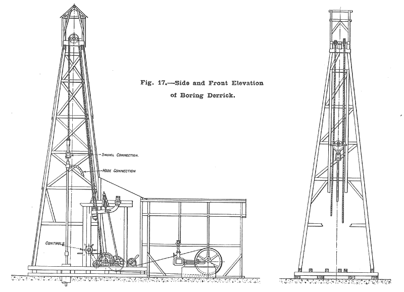
Details of the wooden towers and boring equipment are given in the various drawings. The verticality of the bore-holes is of the utmost importance, since the continuity of the ice wall depends on the holes maintaining regular distances apart. At the top they are 3 ft. from each other, and to ensure verticality as far as possible guide tubes 10½ in. in diameter are securely concreted, in a perfectly vertical position, as shown in Fig. 5, in the outer chamber of the fore-shaft. A deviation of 1 per cent. is permitted in the contract, but actually the deviations have averaged only from 6 in. to 8 in. In view of the relative shallowness of the bore-holes, an elaborate system of surveying them is not necessary. The rate of progress varies considerably, and may be anything between 20 ft. and 150 ft. in a shift of eight hours. All the holes are commenced with an 8-in. H-shaped chisel bit, provided with channels on either side, through which the boring water is discharged. The rods, which are rigidly attached to the bits, have an internal diameter of 2 in., and are fitted with tapered screw joints, as shown in Fig. 10. This enables a connection to be made should the rods become unscrewed, and also facilitates their disconnection when they are withdrawn after the hammering action. They are 25 ft. in length, and have substantially reinforced forged ends to enable them to withstand the heavy usage. They are suspended from the walking beam by suitable swivelling clamps, the rotation being done by hand in a very simple manner, as shown in Fig. 6, with a short wooden lever gripped in a loop of rope. Excessive jarring is obviated by the use of helical springs through which the motion is conveyed. A 25-h.p. steam engine provides the Power and about 90 blows are struck per minute. The length of the stroke can be varied from 6 in. to 12 in. Two of the steam engines are by Continental makers and the third, which is by Ruston & Proctor. has cylinders 7 in. in diameter by 12 in. stroke. It drives the countershaft illustrated in Fig. 14, which is fitted with a plate clutch enabling the eccentric actuating the boring rods and the winch for raising them to be thrown in and out of action instantly. This delicacy of control is essential to the rapid handling of the rods, and further guards the machinery against injurious shocks in the event of any jamming. The engine throttle, the clutch and the change-over gears from the boring to the hoisting are all operated from the front of the tower in immediate view of the top of the bore-hole.
Water is injected at the rate of 4,000 gallons per hour, quadruple-acting pumps being used for this purpose. That illustrated in Fig. 8 is by Tangye Limited, whilst the others are by different Continental makers. Each is provided with a galvanised supply tank situated immediately outside, and this is kept full from an elevated tank of about 8,000 gallons capacity. Owing to the loss of the boring water in the gullets of the limestone, a constant fresh supply is required. To ensure this supply it has been necessary to have an electrically-driven centrifugal pump placed on the shore and a 6-in, pipe has been installed to convey the sea water to the storage tank. Surplus water is led to a reservoir which has been constructed to serve the boiler and condenser plant and afford a reserve in case the shore supply should temporarily break down. This security is essential and the colliery company is naturally held responsible for the regular supply of steam and boring water. The reservoir has a capacity of 250,000 gallons, and a Tangye pump having 8-in, connections, driven by a small Belliss & Morcom steam engine, raises the water, when necessary, to the elevated tank. A 4-in, ring main from this tank encircles the shaft, and connections are made at convenient intervals to the pump supply tanks. Steam is supplied by a similar main from which 2-in, connections are made to the engines and pumps. Practically all these details can be distinguished in the general view given in Fig. 2.
The 8-in, diameter hole is carried down as far as possible until progress is difficult — generally about 300 ft. — when it is changed for one 6 in. in diameter. On the completion of the boring the freezing tubes are lowered into the hole and the lining tubes are withdrawn. The outer freezing tube is 5 in. in diameter by 30 ft. in length, and of course is fitted with a securely closed end, since obviously the leakage of any of the freezing mixture into the strata would be disastrous and would jeopardise the entire sinking operations. A test is made after every two lengths are added, the tubes being submitted to a pressure of 300 lb. per square inch. The inner circulating tubes have a diameter of about 2 in. and consist of ordinary, externally socketed pipes.
Other Equipment.
As yet the freezing equipment, winding engines, &c., are in process of erection, and it is proposed therefore to leave these items until a later date when sinking in the frozen strata is actually in progress. It may be mentioned, however, that the present steam requirements are met by two Woodeson water-tube boilers, each having an evaporative capacity of 20,000 lb. per hour. Eventually the battery will consist of six such units. In sinking the permanent winders will be used, these being of the steam-driven type manufactured by Robey & Co. Ltd. Power will be provided by a B.T-H. mixed-pressure turbo-alternator, which will be interconnected with the power stations at the company's Seaham and Dawdon Collieries.
Already large quantities of concrete have been used in the various foundations, and further considerable quantities will, of course, be required when the shafts are walled. The company is thus fortunate in having an excellent supply of gravel in the immediate vicinity of the sinkings. It is obtained from an excavation to the north of the pits and is brought to the colliery by a full-gauge permanent way, which will eventually link the company's own lines to the L. & N.E.R. at Hall Dene Station. There is very little top cover and the bed averages about 4 ft. in thickness. At present about 30 tons are consumed per day; it is filled into 22-cwt. kibbles by hand, and these are emptied into sidetip wagons by a steam travelling crane. A No. 1 "Victoria" concrete-mixer, by Stothert & Pitt, of Bath, is in use. Bricks for the buildings, and later for shaft walls, are obtained from a new plant which has been erected at Seaham Colliery, capable of producing 20,000 per day, excellent qualities of clay being available from the various seams.
The sinkings are now linked by rail to Seaham Harbour, and the heavier equipment is brought on the spot by this means. A word of praise must, however, be given to the short-wheelbase Pagefield lorries, of which the company possess five, for the yeoman services they have done in conveying the mass of materials brought to the site. The short wheelbase greatly facilitates manoeuvring in a congested dumping ground, and the general substantial build enables them to withstand extremely heavy usage in carrying weighty material over the rough unformed roads incidental to new works of this kind.
Drawings and Photographs accompanying the article


Article reproduced from a copy of the magazine held at National Mining Museum Scotland, Newtongrange, Midlothian.




 Contains public sector information licensed under the

