


 |

|

|

| |
 |
 |
|||

April, 1926
Sinking in Durham by the Freezing Process
Drawings and Photographs accompanying the article
| Sample | Description |
|---|---|
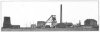 | Fig. 1 — General View of the New Winnings at Present Stage of Completion |
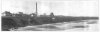 | Fig. 2 — View of Colliery, showing Proximity to Sea |
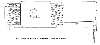 | Fig. 3 — Diagram illustrating Principle of Freezing Process |
 | Fig. 4 — Plan of Boreholes at Vane Shaft |
 | Fig. 5 — Vane Shaft: Sections through Ice Wall, 200, 400 and 535 ft. |
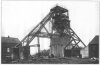 | Fig. 5 — Headgear at the Tempest Shaft with Temporary Supports for Sinking Engines |
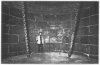 | Fig. 7 — Interior View in Tempest Shaft, taken during the wedging of the joints, showing Junction of Brickwork and Tubbing |
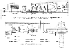 | Fig. 8 — Diagramatic Lay-out of Plant similar to that used for Congelation of the Vane and Tempest Shafts, Londonderry Collieries Limited |
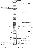 | Fig. 9 — Section of Strata given by Test Hole |
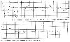 | Fig. 10 — Diagram Showing the Variation of the Water Level in the Tempest Shaft |
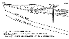 | Fig. 11 — East and West Section showing Disposition of Water-Bearing Strata in relation to Coal Measures |
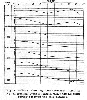 | Fig. 12 — Chart showing Temperature taken in No. 12 Boring, Tempest Shaft, while the adjacent boring received the cold solution |
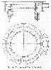 | Fig. 13 — Elevation and Plan of Foreshaft |
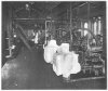 | Fig. 14 — Brine Pumps in Freezing Station |
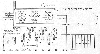 | Fig. 15 — General Plan of Freezing Installation, Seaham Harbour |
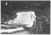 | Fig. 16 — View above the Refrigerating Tanks |
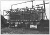 | Fig. 17 — The Ammonia Trickling Condenser for U1 |
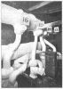 | Fig. 18 — View in the Foreshaft, showing Ring Mains and Branch Pipes to Boreholes |
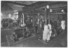 | Fig. 19 — General View of Freezing Station |
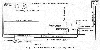 | Fig. 20 — Circulation of Cooling Water |
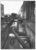 | Fig. 21 — Warm and Cool Water Wells adjacent to the Freezing Station |
Article reproduced from a copy of the magazine held at National Mining Museum Scotland, Newtongrange, Midlothian.




 Contains public sector information licensed under the

