


 |

|

|

|
|
 |
 |
|||
| Colliery Engineering | April, 1926 |
"The Freezing."
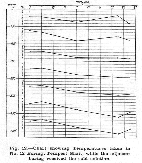
The peculiar conditions prevailing at Seaham thus decided the Société de Fonçage de Puits Franco-Belge to make considerable modifications in the usual practice. Previous to the Seaham Sinkings it was the custom to circulate the cold solution through all the borings simultaneously for the commencement of the freezing, the ice wall thus growing around each freezing tube until the separate cylinders joined together and finally overlapped. The method adopted at Seaham was to put two borings only into circulation at the commencement, one on the west side of the shaft and the other on the east towards the sea. Circulation in these two holes was maintained until the temperature of the four adjacent holes was found to be sufficiently low. These four holes were then put into circulation until the temperature of the next four adjacent holes was sufficiently low to take the solution, this sequence of operations being pursued until the ice wall, thus growing in four different directions, finally joined at the two sides. The graph in Fig. 12 gives an example of the temperatures taken at different depths in the borings.
Among the advantages of the method of procedure just described, may be mentioned :—
| (1) |
When the last freezing tubes are put in circulation there is absolute certainty that the ice wall is completely closed.
| |
| (2) |
It is possible to ascertain the disposition of the frost in the ground, to alter it if necessary, and to bring at the proper time and place the right quantity of coldness required.
|
It is quite an easy matter — by knowing the temperature of the brine as it enters and emerges from the boring, and measuring the quantity of brine in circulation through each boring — to ascertain the quantity of coldness going into the ground, but it has hitherto not been possible to know exactly how the coldness was being distributed, nor how to control and assure this distribution. Quite possibly, the ice wall may be formed perfectly at a certain depth while at another depth the quantity of frost may be very small indeed, and unless the fault is rectified, a hole is left in the wall. Observation of the temperatures in the adjacent borings at once gave a means of following the distribution of the coldness at different depths, and it was consequently possible, when necessary, to counteract the factors which modified the distribution. Control is effected by an ingenious device which is capable of performing the following five operations :—
| (a) |
Direct circulation of the brine in one or more boreholes.
| |
| (b) |
Reversed circulation in one or more of the boreholes.
| |
| (c) |
Direct circulation in one or more of the boreholes with independent circulation in one or more of the boreholes at the same time.
| |
| (d) |
Direct circulation in one or more of the boreholes with reversed circulation in one or more of the boreholes at the same time.
| |
| (e) |
Direct circulation in one or more of the boreholes with, at the same time, a partially-cooled circulation in one or more of the boreholes.
|
A remarkable example showing the degree of exactness with which the coldness was controlled is afforded by the diagram (Fig. 12) referring to borehole No. 12. It had been decided by the Société de Fonçage de Puits Franco-Belge to make quickly an ice wall of the same thickness from the top to the bottom throughout the whole depth of the ground to be frozen. An examination of the temperatures shown in Fig. 12, which are taken from November 9 to 24, shows that the greater part of the coldness was sent to the bottom of the circuit. This inferred, of course, that the ice wall would be forming in greater thickness at the bottom than the top, and as soon as this was established corrective measures were taken and the distribution of coldness changed. Consequently, on November 26 it will be seen that the distribution of coldness was equally intense at all points. The temperature at the bottom had risen, and the temperature at the top had fallen quickly midway there was no appreciable change. The ice wall was then being formed at an equal rate throughout the entire depth.
The Freezing Station.
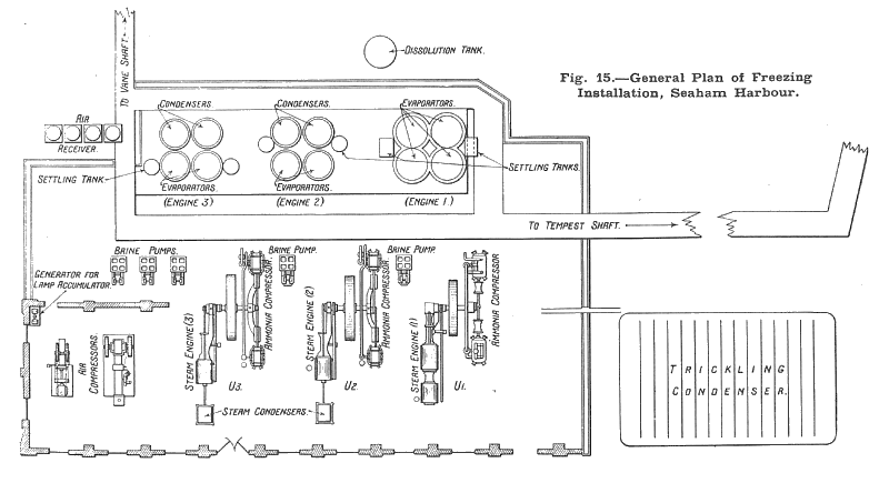
Fig. 15 shows the general lay-out of the freezing station. The plant, which has a refrigeration power of 540,000 negative calories per hour at -20° C., consists of the following equipment :—
| (1) |
One freezing engine having a capacity of 300,000 negative calories at -20° C. per hour, composed of two double-acting ammonia compressors driven by a tandem, compound, condensing steam engine. The engine is provided with Corliss valves and develops 300 h.p. at a speed of 95 r.p.m. This unit is indicated by U1 on the plan, and has four evaporators — two groups of two each, working in series and a trickling condenser. The steam cylinders are 14 in. and 25 in. in diameter, and have a stroke of 28 in., the ammonia compressor cylinders being 15 in. in diameter by a 22-in. stroke.
| |
| (2) |
Two freezing units (U2 and U3), having a capacity of 120,000 negative calories each at -20° C. per hour, comprising steam-driven, double-acting horizontal compressors running at 75 r.p.m. The engines develop 150-h.p., and are fitted with Corliss valve gear. Each unit is provided with two ammonia condensers and two immersed condensers. The steam cylinders are 18 in. in diameter by a 36-in, stroke, while the compressor cylinders are 12 in. in diameter by a 20-in, stroke
| |
| (3) |
Five double-acting duplex brine pumps having steam cylinders 12 in. in diameter, the hydraulic cylinders being 10 in,. in diameter and a 10-in. stroke.
|
In the same building there are two steam-driven air compressors, having a total capacity of 1,000 cubic ft. of air per minute, to provide air for the pneumatic shaft drills. Also, there is an electric generator, with charging board for the electric lamps used by the sinkers.
From the freezing station to the shaft the cold solution is carried in pipes arranged in special trenches, as shown in Fig. 15. On arriving at the shaft it is properly distributed to the borings by circular 'bus pipes, from which connections are branched, fitted with valves and cocks. These connecting pipes are made of lead to allow for contraction produced by the cold. There are two main and two auxiliary pipe rings.
Meters are fitted to register the total quantity of brine in circulation and the quantity passing through each engine and circuit, and thermometers are placed at positions in the plant to ensure perfect thermal control of the whole process. The brine consists of a solution of CaCl2 having a density of 1.25.
Danger signals are arranged to give immediate indication of any leakage of the brine into the ground, in order that any trouble of this kind may be rectified without delay.
The Cooling Water.
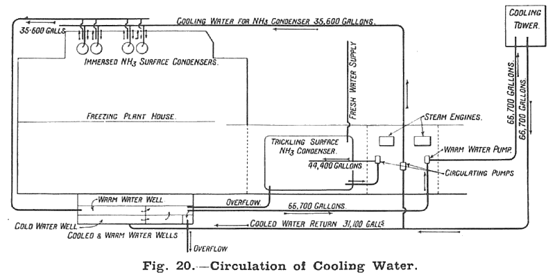
When it is considered that all the heat that was to be abstracted from the ground to congeal it eventually passes into the cooling water of the ammonia — first through the medium of the brine and afterwards by the gas itself — it will be readily understood that an abundant supply of cooling water is necessary. At Seaham Harbour, where fresh water is not abundant, a "Premier" cooling tower has been erected which cools the water from the ammonia condensers as well as the steam condensers of the engines, and only a relatively small quantity of additional fresh water is consequently required for make-up purposes. Fig. 20 shows the arrangement of the cooling pumps, condensers, cooling tower, and the various pipe lines. It will be observed that three centrifugal pumps are in operation. The first keeps an independent circulation on the trickling condensers U1, while a second unit conveys the warm water from the well to the cooling tower. The cooled water runs from the cooling tower to the cold-water well of the steam condensers by gravity. The third pump is connected to this pipe line by a branch which takes part of the cooled water to the immersed condenser of U2 and U3. Two vertical high-speed steam engines are employed to drive these pumps through shafts and belting. Only one engine is in operation at a time, the other being kept in reserve. A working steam pressure of 120 lb. per square inch is maintained, the colliery company being responsible for the supply.
Sinking Operations.
The sinking work which is now in progress is carried out in the same manner as sinking in ordinary dry ground, except that non-freezing explosives are used. Cast-iron tubbing will be used for lining purposes from the natural drainage level down to the coal measures. From the surface to this water level — a distance of some 80 ft. — the wall will be composed of bricks and concrete. When the shaft is completed the ground will be thawed by pumping warm brine into the borings, and a final wedging of the tubbing joints will then be effected where this is necessary.
Drawings and Photographs accompanying the article


Article reproduced from a copy of the magazine held at National Mining Museum Scotland, Newtongrange, Midlothian.




 Contains public sector information licensed under the

