


 |

|

|

|
|
 |
 |
|||
| Mine & Quarry Engineering | August, 1960 |
Face working methods
Primary drilling of the face is carried out with Halco-Stenuick Mk. I and Mk. II compressed air wagon-mounted down-the-hole drills manufactured by the Halifax Tool Co. Ltd., of Southowram, Halifax. One of the former and two of the latter are owned by the quarry, of which two are in constant use with the third being kept in reserve. One of these drills is depicted in Fig. 2.
The Mk. II is a development of the Mk. I vertical drilling machine and is available in two models-for vertical drilling and for holes from the vertical to the horizontal. The Mk. II has been followed by the Universal Mk. III model, which is capable of drilling holes from the vertical to 20 deg. upwards. This machine, like all the other models, incorporates variable speed control facilitating drilling through broken or fissured ground. Although primarily designed for percussive drilling, all the machines can be adapted for use as a rotary drill when working in shales and softer materials, although in the case of the Universal Mk. III the rotary bit can be replaced by a core barrel for exploratory drilling.
The penetration rate as claimed by the makers is from 6 ft. to 10 ft. per hour in hard rocks, to over 20 ft. per hour in soft materials, with an air consumption of from 75 to 125 cu. ft. per minute. The hole diameter is 4 in. using tungsten carbide tipped, or plain steel cross-bits. The penetration rate at Stainton is 7 ft. to 8 ft. per hour, excluding setting-up time, and the bits are reported to have drilled footages up to 3,200 ft. before resharpening.
Recently a certain amount of the primary drilling has been given to an outside contractor. The machine used has been the Holman tractor-mounted Vole drilling rig and is shown in Fig. 3. This unit comprises a standard Fordson Major industrial tractor to the front of which is mounted a Holman F.M. 13 type air compressor having a capacity of 125 cu. ft. per min. at 100 lb. per sq. in. This is V-belt driven from the power takeoff shaft of the tractor motor. Fitted to the rear of the tractor is the drilling beam of the Climax Vole drill. This consists of a large cradle, at the top of which is a four-cylinder hoist and power-feed motor. Along this cradle slides the four-cylinder motor which rotates the actual drilling tubes.
As with the Halco-Stenuick machines, the "hammer-down-the-hole" principle is employed in which the percussive hammer is attached to the bottom of the first drill tube and remains at the bottom of the hole during percussive drilling. The air is delivered through the tubes and exhausts onto the drilling kit keeping it cool and at the same time ensuring efficient clearance of the cuttings. The machine can also be used for rotary drilling work.
At Stainton the rate of penetration is approximately 10 ft. per hour with a consumption of 1¼ gal. of diesel fuel, and the machine is capable of drilling a 3¼ in. diameter hole to a depth of 150 ft. It may be of incidental interest to refer to the operator's claim for this machine in connection with work on the Doncaster by-pass construction scheme. Here 150 ft. was drilled in soft rock in 12½ hr., including setting-up time, the hole depth ranging from 4 ft. to 10 ft.
Prior to the introduction of the Halco-Stenuick wagon drills, well drills, both diesel and electric powered, were employed for primary blasting. The nature of the rock, however, gave rise to poor fragmentation and their use was discontinued in favour of the present machines. The well drills are periodically inspected, however, and kept in working order.
The quarry face varies in height from 50 ft. to 80 ft. and has a total workable face length of 3,750 ft. of which some 1,250 ft. is presently in use. The limestone beds dip slightly in a southerly direction and in certain parts are almost parallel to the quarry floor.
A primary blast usually comprises up to 20 holes. Current practice is to drill 4 in. diameter holes to a 10 ft. square pattern, normally to quarry floor level. Consideration is, however, always given to the position of joints, fissures and bedding planes and where possible these are utilised to effect improved fragmentation and yield. Where necessary, holes are drilled to 2 ft. below quarry floor level to ensure an even break. Any toe that remains is, however, blasted with Polar Ammon Gelignite in 2 oz. cartridges, initiated in 1 in. diameter boreholes by a No. 6 detonator and safety fuse.
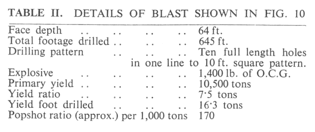
The layout of a typical blast is illustrated in Fig. 10 and details of this blast are given in Table II. The charges in the holes are often decked, each deck charge being initiated by a separate line of Cordtex detonating fuse and these are taped together on the surface. To these are fixed electric detonators connected in series and in cases where up to 10 holes are to be fired all charges are initiated simultaneously.
In blasts consisting of more than 10 holes, the Cordtex lines from the boreholes are connected to a main line of similar fuse. Detonating relays are inserted after every second hole and the main line initiated, by a No. 6 detonator and safety fuse, from either end. This is shown diagrammatically in Fig. 11. The explosive used is Opencast Gelignite in 3¼ in. diameter by 5 lb. cartridges.
Heading blasting was also employed at the quarry, but was discontinued in 1948 owing to very poor fragmentation. This was due to the horizontal bedding planes which were frequently shot out into the quarry leaving the upper beds relatively unbroken. The layout of the mine was to a standard pattern employing four chambers off the back drive of sufficient size to contain the explosive charge. Initiation was by means of electric detonators connected in series. Two detonators were inserted into a priming charge securely positioned in each of the chambers. The back drive and main drive were stemmed for their full length with the broken rock produced during driving of the tunnels, the stemming being strengthened at the drift junction with old sleepers.
Secondary blasting is performed by up to six men operating Broom and Wade, Atlas Copco and Holman hand-held rock drilling machines. Holes 1 in. in diameter are drilled to the required depth and charged with 2 oz. cartridges of Polar Ammon Gelignite, initiation being by means of No. 6 detonators and safety fuses. All explosive products used at the quarry are provided by the Nobel Division of Imperial Chemical Industries Limited. Primer cartridges are made up in advance in a special building sited some distance from the quarry face. Usually up to 80 shots a day are fired, dependent upon the weather, using approximately 10 lb. to 15 lb. of explosive. However, as many as 160 pop-shots a day are not uncommon.
Air hoses feeding the hand-drilling machines are connected to threaded outlets on 8 in. diameter by 2 ft. long steel cylinders. These cylinders, which are provided with legs, are connected to convenient take-off points on the main air lines, a valve being placed between the cylinder and the air line. These units, one of which is illustrated in Fig. 7, are made in the quarry workshops.
In Fig. 13 loading operations may be seen in progress at the face. The machine shown is a 38-RB face shovel manufactured by Ruston-Bucyrus Limited, of Lincoln; it is fitted with a 1¾ cu. yd. capacity dipper and is powered by a 75 h.p. B.T.-H. motor running at 970 r.p.m. Starting equipment and switchgear was supplied by the British Thomson-Houston Co. Ltd. (now known as Associated Electrical Industries (Rugby) Limited), and Foster Transformers Limited, of South Wimbledon, London, S.W.19. This is seen loading stone into one of the four Foden haulage vehicles in use at the quarry.
The other machine used for face-loading operations is a Ruston-Bucyrus 54-RB which is fitted with a 2½ cu. yd. shovel. This excavator, shown in Fig. 12, is powered by 60 h.p. and 23 h.p. motors running at 500 r.p.m. and 650 r.p.m. respectively. The d.c. generating equipment as well as the motors and switchgear was of B.T.-H. manufacture and the transformers were supplied by Foster Transformers Limited.
The distance from the quarry face to the point of discharge into the plant reception hopper, varies from 200 ft. from the nearest face, to approximately 1,500 ft. from the main face. Feeding the primary crusher with the required 800-1,000 tons daily is normally carried out by a fleet of four model FGC5 dump trucks manufactured by Fodens Limited of Sandbach, Cheshire. This vehicle is powered by a four-stroke five-cylinder Gardner 5 LW diesel engine developing 94 b.h.p. at 1,000 r.p.m. It is designed to carry a payload of 20,000 lb., representing a heaped load of 8 cu. yd.; the unladen weight is 7 tons 10 cwt. including body, fuel, oil and water and fitted with the Gardner engine.
The body generally has a in. thick steel floor and ¼ in. side plates reinforced with channel steel sections welded throughout. Those at Stainton Quarries are fitted with an angle iron floor, available as an extra on these vehicles.
The tipping gear is a twin ram, double-acting unit capable of tipping the body fully (to 60 deg.) in 12 sec. The tipping cylinders are mounted in robust cradles on the outside of the frame.
Drawings and Photographs accompanying the article


Article reproduced from a copy of the magazine held at National Mining Museum Scotland, Newtongrange, Midlothian.




 Contains public sector information licensed under the

