


 |

|

|

|
|
 |
 |
|||

December, 1953
The Billingham Mine - Part 1
In the first of a series of articles about the modernisation being undertaken at this anhydrite property of Imperial Chemical Industries, Limited, a description is given of the geology of the area, the two shafts and the improved efficency obtained in percussive drilling by the use of special carriages.
Billingham anhydrite mine, owned and operated by the Imperial Chemical Industries, Limited, is located on the north bank of the River Tees, near Stockton, County of Durham, England. The Billingham works of the I.C.I. is the largest chemical factory in the British Empire, and second largest in the world, occupying a site of about 1,000 acres; the mine is located in the Casebourne division of the works, and provides anhydrite, one of the raw materials essential for the factory.
The factory was started during the first world war, and was developed for the purpose of making synthetic ammonia for explosives. After the war, the plant was bought from the Government by Brunner, Mond and Company (one of the original founding companies of I.C.I.) who proceeded to develop it primarily for the production of nitrogenous fertilisers. Sulphate of ammonia was the first fertiliser manufactured at Billingham, and still is, on tonnage, the principal product. Knowing that seams of anhydrite, of presumed economic workability, existed beneath the factory area, two 13 ft. diameter shafts were started in September, 1926, and production of anhydrite commenced 14 months later*. At the present time 20,000 tons are mined per week. There are 200 miles of underground roadways, and one square mile of workings.
Geology
The factory area is overlaid with a thick layer of glacial drift. As will be seen from Fig. 1 this is followed by 400 to 500 ft. of Bunter sandstones and Permian marls. Below this comes some 900 ft. of Permian series, in which the anhydrite and rocksalt deposits occur. From mining experience up to 1939, these beds showed an even dip of about 1 in 20 in a direction of S.47° E., but in recent years variations in direction and dip have been encountered, and red marls have intruded in the roof. Below the Permian, at an approximate depth of 1,300 ft., there exists a Carboniferous floor.
Of the Upper, Main, and Lower anhydrite seams, the one being mined is the Main seam consisting of 15-20 ft. of massive anhydrite averaging 90 per cent. purity. The working floor is of magnesian limestone or dolomite.
The mined anhydrite is a blue-grey stone, translucent in thin section. It has a specific gravity of 2.9 and a hardness of 3 to 4 on Moh's scale. A representative average analysis of the mine output is:—
| CaSO4 | 90-94 per cent., of which up to 5 per cent. may be gypsum |
| Dolomite | 0.5 per cent. |
| SiO2 | 2.5 per cent. |
| NaCl | 0.025 per cent. |
plus traces of ferric oxide, alumina, muscovite, biotite, hornblende and fluorite.
The anhydrite seam is normally quite dry, being protected from the heavily water-bearing Trias Bunter sandstones by the overlying layer of Permian red marls. Small quantities of water, methane, and hydrogen sulphide are, however, liable to be released when the underlying dolomite is penetrated.
Shafts
The mine is served by two shafts, No. 1 is the downcast and contains two 4½-ton skips, while men and materials are wound through the upcast No. 2 with double-decked cages.
Both shafts were sunk by The Cementation Co. Ltd., and were bottomed after 14 months' sinking at an elevation of 850 ft. below surface. Both headframes were supplied by Head, Wrightson & Co. Ltd. When passing through the sandstones 600 gallons of water per minute were made in the shafts, necessitating lining with reinforced concrete through the waterbearing strata. Below this area, the shafts were lined with plain concrete.
The anhydrite was intersected at 778 ft. from the surface, sinking being continued to give depth for the installation of a 180-ton bunker loading pocket. When sinking through the dolomite, methane and H2S were encountered, necessitating additional auxiliary ventilation, and hourly tests of the conditions on the shaft bottom.
No. 1 shaft is of 13 ft. internal diameter, and the layout of skips, compressed-air main and pump line is shown in Fig. 2. Skip guides are of 60 lb. B.S. F.B. rail throughout. Skips, operated in balance, are 3 ft. 4 in. wide and 8 ft. 3 in. high; they are of the overturning type, hinged at the bottom.
At the bottom of the shaft, spillage is collected by means of a plated chute covering both compartments and this delivers into a standard mine tub. Tubs of spillage are hauled by rope haulage up an inclined access rise from No. 2 shaft and the material is transferred to the stone circuit at the tippler.
Located at the same elevation as the spillage drift is the main pump room and sump. Duplicate sets of Mather and Platt Plurovane 100 g.p.m. (2,300 r.p.m.) turbine high-lift pumps with individual motors are provided. At the present time, the total inflow to the sump is of the order of 8 g.p.m. and the pumps are only operated two to three hours per week. This inflow indicates the efficiency of the sealing-off of the sandstone waters; however, adequate pump capacity is provided in case of an emergency breakthrough of waters in that section of the shaft passing through the Bunter sandstones.
No. 2 shaft is of 13 ft. internal diameter. Double-deck cages 4 ft. 3 in. wide, 6 ft. 9 in. long and 14 ft. high are operated in balance in this shaft. These dimensions allow a 7 ft. deck clearance. Rails to a 2 ft. 6 in. gauge are laid in each floor, and tub-retaining catches to engage on the wheels are provided. Landing keps are installed a surface; the existing landing, providing access to the Main West Level via an incline and ventilation doors, is being replaced by a new system on which driving has commenced.
Although the small diameter of the two shafts is responsible for 2.2 out of the 2.3 in. w.g. shown at the main fan, unit power costs are so low that the capital expenditure for larger shafts is not warranted. Skips, cages and ancillary shaft equipment were supplied by Head Wrightson and Co. Ltd.
Mining methods
Although all workings at Billingham are carried on by a pillar-and-stall mining method, great changes have been undertaken in recent years, to increase production and output per man shift, and to lower operating costs. At the time of our visit, the mine could be said to be in the transition state between an "old" method by which some 50 per cent. of the total production at the present time is being obtained, and the "new" method which has been proved successful and is in the process of being fully implemented.
In the old workings a top-heading-and-bench method was established using electric scraper loaders, rope auxiliary haulages, and trolley locomotives for the main haulage. Roads of 18 ft. width are driven along and at right angles to the strike at 60 ft. centres, leaving pillars 42 ft. square at 60 ft. centres and giving an extraction of 50 per cent.
In anticipating the new method, which was to include the adoption of diesel-truck haulage, and Joy loaders, two experimental areas in the scraper-loader section were opened up with 24 ft. wide roads at 75 ft. centres eight years ago; this left pillars 51 ft. square, while maintaining the same extraction rate of 50 per cent. These trial workings gave no greater roof trouble than with the 18 ft. roads, and the management were able to plan for the new working panels without fear of the consequences; it is to this layout that the present workings in the new section are being driven.
Fig. 4 shows a plan view of part of the underground workings. It demonstrates how the first new panel (No. 1) was developed from the scraper loading section. To the east is panel No. 2, in which work by the new method is now proceeding.
To the north in panel No. 1, a zone of 1 in 4 gradients was encountered, and although such gradients made working conditions difficult, it was found possible to work the Joy 11 B.U. loader and the diesel trucks on this grade. In the same general area, a marl roll has intruded into the roof of the anhydrite, thinning out the seam and creating the very poor roof conditions not common in the rest of the mine.
It will be noted from the various illustrations to this article that there is a complete absence of timbered roof support. Where poor back is doubtful, resort is made to roof bolting with 1 in. steel bolts, and Rawlplug K21 shields. These are driven 2 ft. above the suspected parting necessitating a maximum roof bolt length of between 4 and 6 ft. One area in the scraper loading section is at present using roof bolts at 4 ft. centres. A stock of roof bolts is maintained underground for immediate use should conditions warrant. Experiments are being carried on with the technique, first introduced to Billingham some 15 years ago as a means of supporting trolley wires; investigations to date reveal that the taper of the roof bolt wedge needs to be much reduced for use in rock as hard as Billingham anhydrite to obtain the maximum strength.
The salient differences in efficiency between the mining methods are shown in the table on the right.
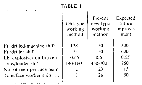
It should be emphasised that much of the equipment at present in use with the new method is of a temporary nature, having been installed to maintain production while the mine is changing over, and to permit full study of the problems relating to each individual piece of heavy machinery. Much of the present equipment is of American manufacture, but in recent years development of British-made equipment has proceeded in such a way that in the future the Joy loader may be the only imported item utilised in the new method. A feature of the new system of working is that many men in a panel will be interchangeable, and the management are training their labour to this ideal.
* "Billingham Mine," by G. Eland Stewart, B.Eng.(Min.), Transactions of the Institute of Mining and Matallurgy, Vol. LVI, p. 113.
Drawings and Photographs accompanying the article


Article reproduced from a copy of the magazine held at National Mining Museum Scotland, Newtongrange, Midlothian.




 Contains public sector information licensed under the

