


|

|

|

|
|
 |
 |
|||
Sinking
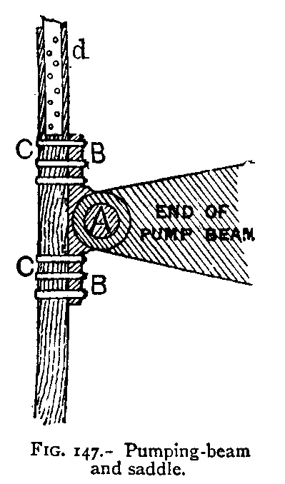 Sinking-Pumps. – The pumps most commonly employed in sinking pits are shown in Fig. 137. On the crank-shaft of the steamengine is a small spur-wheel or pinion, which gears into another spur-wheel three or four times the diameter of the pinion. On the same shaft as the large wheel is a crank or disc, with three holes for a crank-pin, which can be placed in either hole to make a long or short stroke as required. A connecting-rod from the crankpin gives movement to beams shaped like the letter T inverted, or the letter L, at the pit-top. The pump-rods are attached to these beams by the method shown in Fig. 147. The beam is made of two sides, a pin, A, passing through both; this pin also holds a saddle, B, which can turn upon the pin. By means of clamps C C. this saddle is fastened to the pump-rod. These pumprods are of wood, and from 4 to 12 inches square, according to the size of the pumps, 6 inches square being a suitable size for pumps 14 inches in diameter working from a depth of 50 yards. The pump shown in Figs. 148 and 149 is that kind usually called a bucket-lift. The pipes are all made of cast iron. The bottom pipe has a rounded end perforated with holes, and called a wind-bore; this rests on the ground, standing in the water ; if the water should not be deep enough to cover all the holes, those above the water may be plugged, so as to prevent wind from drawing in. Above the wind-bore is the clack-piece; the clack-valve is shown also in Fig. 148 (1) 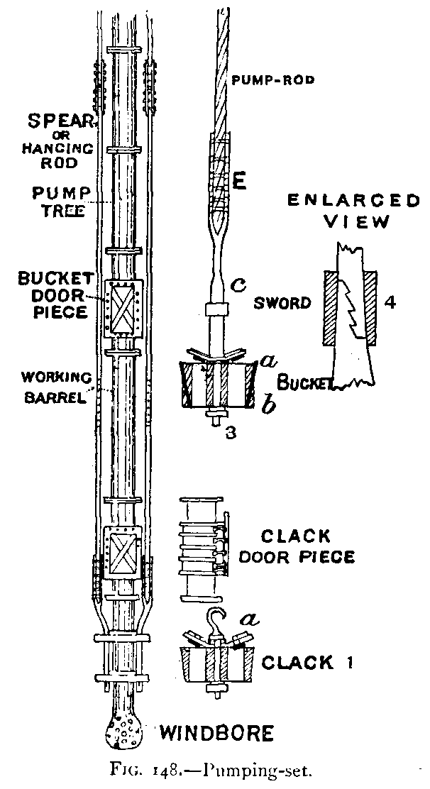 . The shell, or valve-seating, is of cast iron, tapered on the outside to fit into a tapered recess in the clack-piece. There are two openings for the water, both of which are covered by a wrought-iron plate, which is the valve. This wrought-iron plate is riveted on to a piece of tough leather, which covers the whole surface of the shell, and is fastened down by a collar on the hook a, which passes through the shell; this leather forms the hinge, and also makes a soft bed for the valve, which would not otherwise be water-tight. A hook or bow is used for the purpose of lowering or raising the clack. The cast-iron door can be taken off when it is necessary to change the clack. It has sometimes happened that the door has been taken off, and could not be put on again before the water had risen up so that the clack was useless. There is often another clack-seating above the door, where the clack could be placed in case the lower clack was rendered useless in any way. To avoid the risk of not having the clack-door on or properly tight, there is sometimes no clackdoor, and the clack has to be drawn up to and lowered from the surface every time it is changed. Above the clackpiece comes the working barrel; this pipe is abotit 10 feet long, it is accurately bored, and is the cylinder in which the bucket works. |
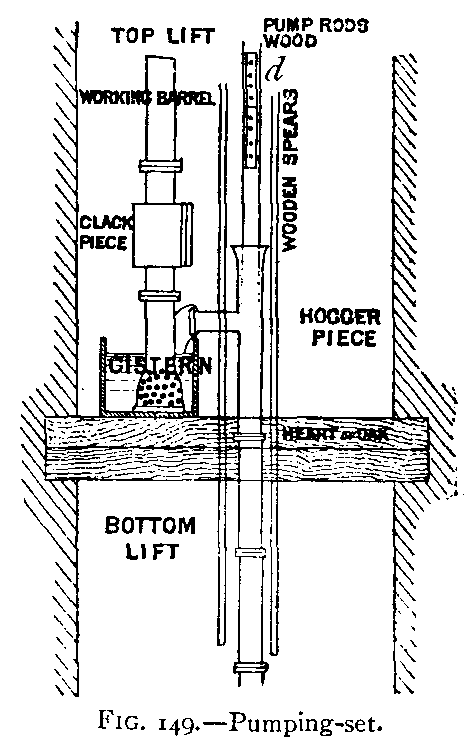 Above the working barrel is a bucket-door piece, a short pipe 4 to 6 feet long, in which is a door similar to the clack-piece door. At this door the bucket can be taken out and replaced. This door is also sometimes omitted for the same reason as given above for dispensing with the clack-piece door. Above the bucketdoor piece are the ordinary "pump-trees." The "pump-tree" is a pipe, so called because it was originally made by boring out the trunk of a tree. It is generally made of cast iron with flanges, and should be at least 1 inch in diameter larger than the working barrel, so that the bucket can be easily withdrawn or lowered, and the flanges should be faced in the lathe, so that the joint can be easily made water-tight with indiarubber rings. Bolts and nuts are used for fastening the joints. Formerly pumptrees were not faced in the lathe, and the joints were made water-tight by means of a thin wrought-iron ring, or washer, rather larger in internal diameter than the bore of the pump-tree. This ring was wrapped with flannel, and placed between the two flanges, and when the bolts were tightened the flannel served to make a water-tight joint. At the top of the pump-trees is the hogger-piece (see Figs. 149 and 137). This is a branch pipe for the delivery of the water, and is belIed out at the top to prevent the water overflowing when the bucket is lifted. To the hoggerpiece is attached a large flexible tube frequently made of leather, which conveys the water into the drain. Pipes of wrought iron and steel are sometimes used instead of cast iron. They have generally a riveted longitudinal seam, and the flange is riveted on by means of an angle iron, which is riveted round the pipe and also to the flange. These pump-trees of wrought iron or steel are very much lighter than cast iron, owing to the greater tensile strength and trustworthiness of wrought iron. |
|
Bucket. – The bucket is shown in Fig. 148 (3). The valves are similar to those in the clack. The water is prevented from slipping between the bucket and the working barrel by a leather packing-ring, a. This ring is held tight by a tapered iron ring b driven on from below. When the bucket is lifted, the water on the top, pressing on the inside of the leather ring, forces it open and against the sides of the working barrel, and until this leather ring is worn out the water will not slip past the bucket to any large extent. The bucket is attached to the rods by a toothed iron or steel bar, called a sword, shown in Fig. 148 (3) c and (4), over which a ring is driven to keep the teeth in their places. The sword is attached to the pump-rods by the iron fork and by bolts, as shown in Fig. 148 (3) E. The rods, which may be in lengths of 20 or 30 feet, are joined one to the other by wrought-iron plates and bolts (Figs. 147 d 149 d, and 150 d d). Whilst the working barrel is 10 feet long, the stroke of the bucket in a sinking pit seldom exceeds 6 feet, and is sometimes only 2 feet. As the pit gets deeper the pumps have to be lowered. When first fixed the bucket works to the bottom of the working barrel, but when the pumps have been lowered it works at the top. The bucket can he lowered by undoing the clamps above mentioned, and letting down the required length of rod, fresh rods being added at the top as required.
|
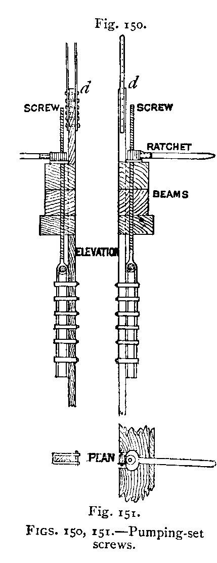 Pumps are frequently suspended by ropes, or chains, or wooden rods called spears; these latter are shown in Fig. 148. They are clamped to the wind-bore, and at intervals are attached to the pumps above by co1lars. The upper end of each is attached by clamps (Fig. 150) to a large screw. This screw-thread is from 6 to 10 feet in length (on a rod 6 feet longer than the screw) – the longer the better – and is from 3 to 4 inches in diameter, with a square thread chased. At the lower end of the rod is a head with an eye in it. To this eye is suspended by a pin the clampingpiece to which the rods are fastened. The screw passes through a nut, below which is a large washer; this washer rests on a strong beam or beams (Fig. 150). As the pit gets deeper the pumps are lowered by unscrewing these nuts. A long lever and ratchet is commonly used for this purpose. If the nuts were attached by gearing to a small steam-engine, the raising and lowering of the pumps would be more expeditiously and cheaply effected. When pumps have been lowered the length of the screw, the clamps are loosened, the screws run up, and the clamps again tightened to a higher part of the spears. Instead of this system of screws, capstans and pulleys are sometimes employed (see Fig. 155). In other the pumps are not suspended, but are fixed to cross-bearers In the shaft, and the wind-bore slides over a pipe attached below the clack-piece, which has been turned in the lathe so as to make an air-tight joint with the sliding wind-bore. 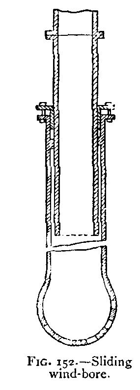 The joint is completed by means of a stuffing-box (Fig. 152). As the pit gets deeper the wind-bore can fall down the length of the slide, which may be 10 feet. In order to add fresh pumps, it is necessary to break the joint above the bucket-door piece, and lower that and the pipes below by means of the capstans sufficiently to take in a 9-foot pipe, the slide being run up to the top of its length. |





 Contains public sector information licensed under the

