


|

|

|

|
|
 |
 |
|||
Sinking
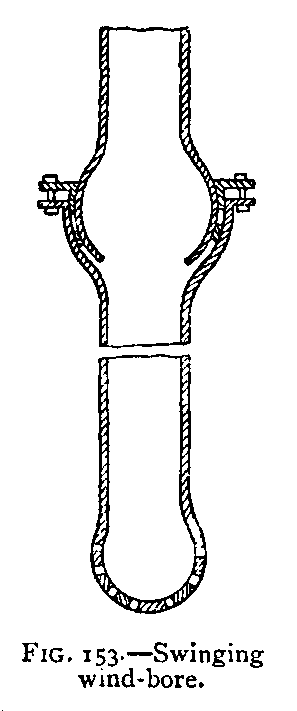 Swinging Wind-bore. – It is necessary to blast the ground immediately underneath the wind-bore. Where the pumps are suspended by spears, they can be swung from one side of the pit to the other, but where they are fixed, this cannot be done. To overcome this difficulty a swinging wind-bore (see Fig. 153) is sometimes used. This is made on the principle of a ball-and-socket joint, and it can be moved a distance of or 8 feet in
either direction. When blasting, the pumps are protected as much as possible by wooden planks from the effect of stones thrown across the pit. |
|
It is seldom that an ordinary pump is employed to lift the water a greater height than 70 or 80 yards. When the pit exceeds that depth, another set of pumps is employed (see Fig. 149), which pumps the water from the bottom into a cistern from which the upper set of pumps takes the water to the surface. Where there is a large quantity of water, several lifts have to be put in. As many as five lifts have been employed at one time working from the bottom, and these pumps are sometimes 20 and even 30 inches in diameter. When dealing with large quantities of
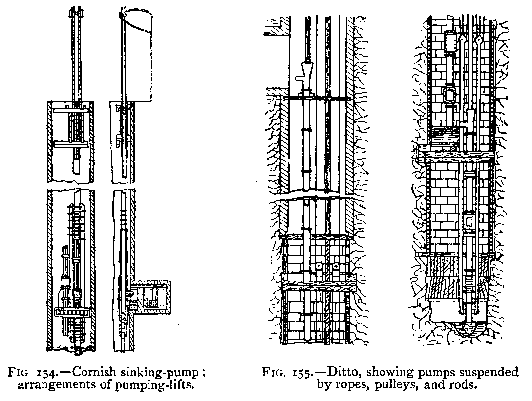
water, the method of pumping may be modified by the consideration that the pumping-engines will be only temporarily required during the sinking, and that the water will afterwards be tubbed back, and the pumping-engines become useless. If, on the other hand, the pumping-engines will be permanently required, machinery of a permanent and economical kind may be erected. The kind of pumping-engine known as the Cornish has a great reputation for economy, and is therefore employed sometimes as a sinking-pump (see Figs. 154 and 155).
|
|
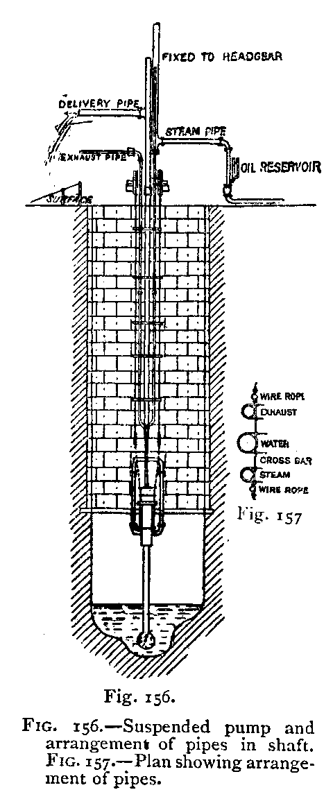 Where the pump is only temporary, it has of late years become common to suspend in the shaft steam-pumps by means of wire
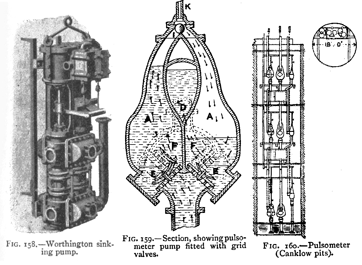
ropes (Fig. 156). The steam is taken down the pit in wrought-iron pipes with a sliding joint, so that the engine can be lowered as required. The delivery-pipe of the pump is free to be lowered down. The suction-pipe is sometimes a flexible tube or has a sliding joint, so that it can be kept at the bottom of the pit, or the engine is constantly lowered as the pit is deepened. These pumps are convenient, because, owing to the steamcylinder and pumping-cylinder being fastened together on one iron plate, they require no external support, and they may be worked at a great pace with comparatively little risk of fracture one of these pumps may deliver as much as 1000 gallons a minute. Three sets of pipes have to be suspended in the shaft—steam, exhaust, and water. These may be attached to cross-bars, as shown in Fig. 157. The delivery-pipe is brought up, say, 10 feet above the bank, and also the exhaust-pipe (see Fig. 156). As the pit is deepened, the pump is lowered by the capstan-rope by which it is suspended. The steam-pipe, having a slide at the pit-top, lengthens. The delivery and exhaust pipes, not being attached at the top, are free to follow the pump downwards. Fig. 158 shows another kind of pump, which may be
suspended in a similar manner. There are a variety of pumps used for this purpose, and those shown in the illustrations are not necessarily better than any of the others. The pulsometer (see Fig. 159) has also been used in shaft-sinking. As it is not suitable for high lifts, it is necessary to place one above the other; the bottom pulsometer delivering into a cistern from which the next one takes its water, and so on up to the surface. Fig. 160 shows a method that has been adopted in sinking the Canklow pits of Sir John Brown and Co. At this pit the quantity of water met with near the surface was very great, amounting to between 2000 and 2500 gallons a minute. Nine pulsometers were employed in three
tiers, each pulsometer raising the water to a height of about 72 feet. The steam was taken down the pit in pipes from boilers worked at a pressure of 80 lbs. per square inch, the sliding steampipe being used for the lowest set of pulsometers. The three lowest pulsometers were suspended by chains from three crab-winches on the surface; the two upper tiers of pulsometers were fixed on wooden beams. At this colliery, after the pit was completed, the water was kept out by tubbing, and the pulsometers were then no longer necessary. There is no way of ascertaining the amount of water delivered by a pulsometer, except by measuring the quantity delivered; but with regard to ordinary pumps the probable
quantity of water may be calculated from the diameter of the working barrel, the length of the stroke, and the number of the strokes per minute. |
|
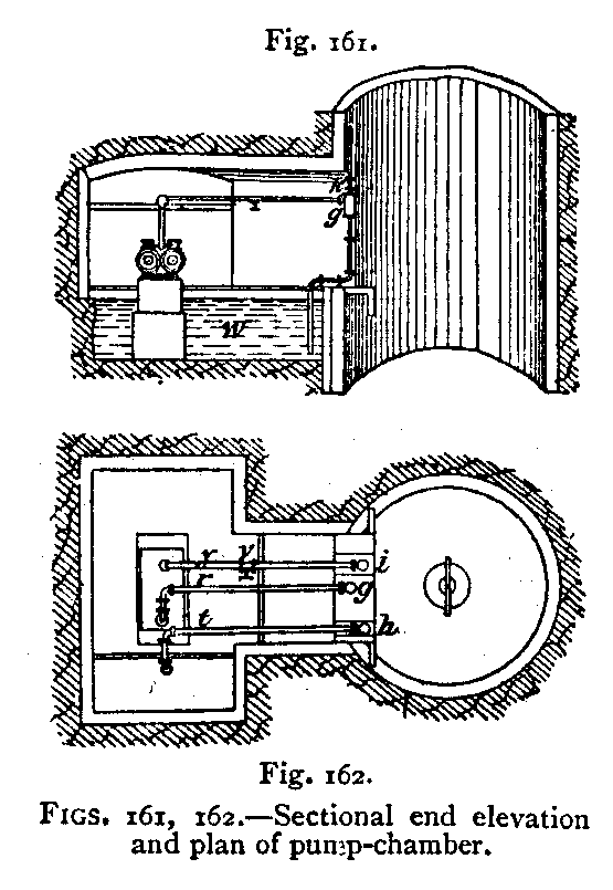 Underground Pumping-Engine. – It is often found convenient, when sinking a pit, to fix a permanent pumping-engine in a chamber by the side of the shaft (see Figs. 161 and 162), the steam being brought down to the engine in pipes. After the steam has done its work, it is sometimes condensed and then passed up with the delivery of water, or it is taken to the upcast shaft, or it is conveyed to the surface in separate pipes or behind a brattice; the advantage of this mode of pumping the water is that the steam and water pipes occupy less room in the shaft than the pumps worked by rods from the surface, and also they occupy no space on the surface. The heat from the steam-pipes and exhaust
steam is useful for ventilating purposes, if they are in an upcast shaft or on the upcast side of the brattice in a shaft. |
|
Where there is a great deal of water, the sinking of two shafts simultaneously facilitates the pumping, because there may be pumps in both shafts; and if the water has to he tubbed out it is highly desirable that all the shafts at the colliery, whether two or three, should be sunk simultaneously, because, if the first shaft was sunk and tubbed, then all the water would have to be pumped at the second pit, whereas, when the pits are sunk together, one pumping does for both the shafts. If, however, the pumping will be
permanent, it is sometimes economical to sink the pumping-shaft in advance of the other shafts; in this way the strata are drained, and the second and third pits may be sunk without any pumping. If, notwithstanding the existence of a pumping-shaft, there should still be water in the other shafts, they may be drained in the manner shown in Fig. 163
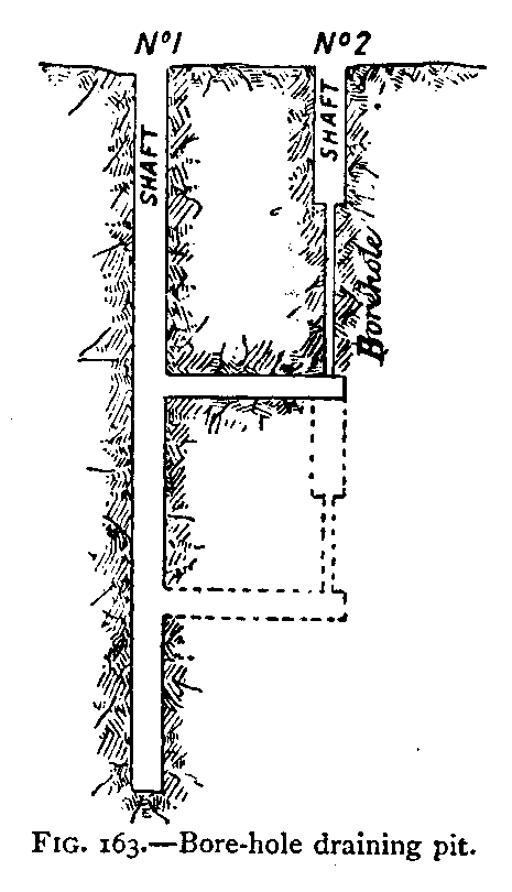 . Here a heading is driven from the pumping-pit under the pits which have to be sunk, and then a bore-hole put down from the sinking pit into this heading, so that any water that is in the shaft runs down this bore-hole, and the sinkers are free from the hindrance of water. There may be some tendency for the hole to be stopped up. To avoid this a chain is sometimes passed through the hole and fastened
above and below; if the chain gets jammed, it may be attached at the upper end to the engine or capstan, and pulled, and in this way the hole is cleared. |
|
The foregoing remarks on sinking are taken from the experience of colliery shafts, but the sinking of shafts for other purposes, such as for iron, tin, or gold mines, is conducted on similar principles. It is, however, common, in the sinking of metalliferous mines, to sink shafts at an inclination from the vertical in the vein and following the vein, so that, whilst the shaft is straight as regards the direction by the compass, it may be crooked as regards its inclination. Where the shaft is inclined, the hoppet, instead of being suspended without guides, is frequently a box on wheels running on or between guides; in the same way the rods from the pumping-engine are supported by rollers. But where metalliferous shafts are sunk in the vein, the sinking is concurrent with the opening out of the mine, and therefore, after the first two or three levels are opened, the sinking of the shaft is gradual, like the development and exhaustion of the mine, and is continued for scores or even hundreds of years.
|





 Contains public sector information licensed under the

