


|

|

|

|
|
 |
 |
|||
Sinking
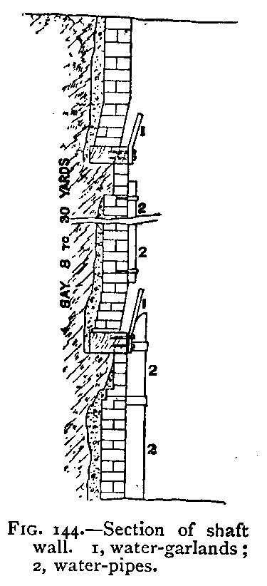 Water Garlands. – In sinking a pit through ordinary ground, water is met with, and the amount of this water soon becomes sufficient to cause a good deal of trouble; in order to prevent it splashing about unnecessarily and hindering the men, it is collected. For this purpose garlands are fastened on to the bricking-curbs (see Fig. 144). These are generally made of sheet iron about 12 inches wide, nailed all round the shaft, so as to make a ring standing 2 or 3 inches out from the brickwork; all the water trickling out of the brickwork must run into this ring; at one place a hole is made in the ring out of which the water can run into a pipe, say 2 or 3 inches square inside, sufficient to carry the water. At the curb below is another garland. The pipe delivers its water into this second garland, which also collects fresh springs; a second pipe goes down from the second garland, which may be larger in size than the first one, because it may have to take a larger quantity of water. In this way the water is conducted to the pit-bottom or to some cistern in the shaft-side. If it goes to the pit-bottom, the wooden pipe stops at the lower end of the brickwork, and a flexible tube (or simple rope) continues it to the bottom, where it delivers the water into the water-barrel. As soon as this barrel is filled, it is wound up by the engine, and the flexible water-pipe is put into another barrel which is ready at the pit-bottom. In this way small feeders of water can be raised. If there is more than a small supply, such as 50 gallons a minute, a separate winding-engine is necessary to wind the water; and if the quantity of water is more than 200 gallons a minute, pumping-engines are usually employed. |
|
Guides. – As a general rule, the sinking hoppet is not attached to guides. After it has been lifted off the bottom, one of the sinkers steadies it, and when it has stopped swinging, it is wound up, and it swings but little on its way.
|
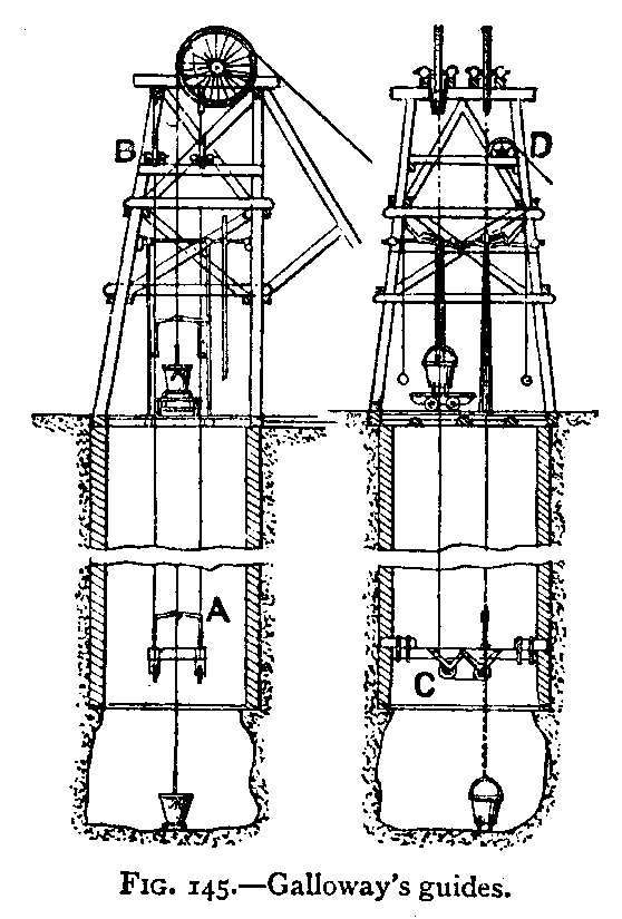 Some engineers, however, prefer to have the sinking hoppet guided. Amongst such methods one designed and patented by Mr. Galloway has been used in South Wales and elsewhere. It s shown in Fig. 145. This system of guiding may be described as follows: Two wire guide-ropes are stretched from the pit-frame on the top to a platform fixed at the bottom of the brickwork in the shaft (see Fig. 145). The crossbar A, with a collar at each end, fits on to these guides; in the centre of the cross-bar is a hole through which the winding-rope passes; beneath the cross-bar is attached the hoppet. When the hoppet is raised, a rubber buffer at the lower end of the windingrope comes in contact with the cross-bar, so that it also is lifted. As the cross-bar is connected with the wire guides, it cannot swing, and the hoppet is also steadied. In lowering the hoppet to the bottom, the cross-bar is arrested by some buffers on the guides just above the platform, but the hoppet continues to descend through an opening in the platform to the bottom of the pit. The wire guides are generally attached to capstans, by means of which they can be raised or lowered, and the platform is used for the masons in walling the shaft. In large pits there may be two hoppets and two sets of guides; in this case there is only one capstan rope for each set of guides (see Fig. 145). One end of each wire guide is fastened to the pit-frame at D, it passes down and under the pulleys C in the pit, then up to the top again over the pulleys B, and thence to the capstan. |
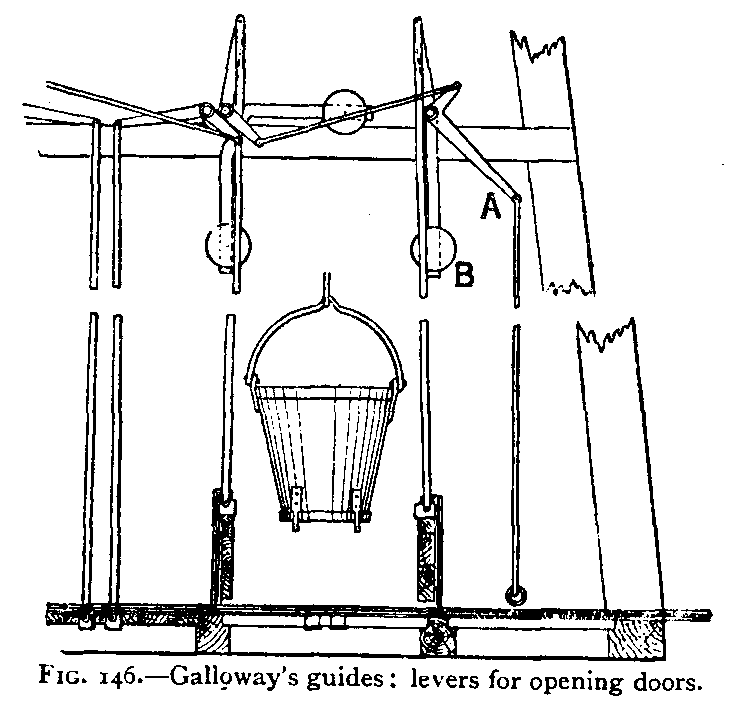 The pit-top is covered over, and there is a pair of doors through which the hoppet can be raised (see Fig. 146). These doors are lifted by means of the lever A and the balance-weights B. When they are open they form a fence for the shaft, the other two sides of the opening having permanent fences. After the hoppet has been raised, the trap-doors are closed, and a bridge run over them, into which the hoppet is lowered. |





 Contains public sector information licensed under the

