


 |

|

|

|
|
 |
 |
|||
| Colliery Engineering | April, 1924 |
Winding Engines.
Steam winding engines of the Semi-Corliss type by Markham & Co. Ltd., are employed for all three shafts; those at South and North pits are duplicate sets having cylinders 36 in. in diameter by 72-in, stroke. The drums are cylindro-conical with a maximum diameter of 18 ft., and are all 11 ft. 6 in. wide.
The various weights involved are as follows :—
| tons. | cwts. | qrs. | |
| Cage, chains and safety hook | 7 | 5 | 0 |
| Winding rope | 4 | 10 | 0 |
| Eight tubs (empty) | 2 | 12 | 0 |
| Coal per wind | 4 | 8 | 0 |
| 18 | 15 | 0 | |
| 6 - in. circular - balance ropes | 4 | 0 | 0 |
| Total on drums | 14 | 15 | 0 |
Fig. 7 shows the winding engine of the East pit, which is precisely similar in type to those already mentioned except that the cylinders are 30 in. diameter by 72 in. stroke. "Tangent" shaft signalling apparatus, by Gents, is in use in all three pits. Current for this purpose is supplied by a ½-h.p. motor-generator, 220/25 volts.
A common steam supply, at a pressure of 120 lb. per square inch, is generated by 12 Lancashire boilers and 2 Babcock & Wilcox boilers. The latter, which are fed with coke ballast and small coal, were originally intended for use in conjunction with the coking plant only, but it has been found more convenient to pool the existing colliery steam supply. For these two boilers a Lassen & Hjort water softener of 4,000 g.p.h. capacity is in use. Three of the Lancashires are 32 ft. in length and have a diameter of 9 ft. 3 in., the remaining nine being 30 ft. long with a diameter of 8 ft. Arrangements are made by which surplus gas from the coke ovens can be consumed in these boilers.
The B. & W. boilers are equipped with balanced draught gear and have chain-grate stokers with overhead bunkers and coal conveyors, with an automatic skip conveyor for ashes. They are shown in Fig. 12.
Hydraulic Decking Gear.
The cages are decked by special hydraulic gear, supplied by Geo. Fletcher & Co., of Derby, by means of which a considerable saving of time is effected. In conjunction with the main cages, which are of double-deck construction, there are two auxiliary cages on either side, which can be raised and lowered by means of vertical hydraulic rams situated underneath, 4 in. in diameter, with a stroke of 7 ft. 2 in.
During winding, empty tubs are placed in position on both levels in the auxiliary cage on the empty side and when the cage has been brought to bank the full tubs on both decks are simultaneously pushed out on the full side by means of rams acting behind the empty tubs in the auxiliary cage. Thus, the cage has its contents changed from full to empty tubs in a very short time. The full tubs in the auxiliary cage run off by manhandling, assisted by a good gradient. During the next wind the full tubs in the upper deck of the auxiliary cage are brought down to bank level and despatched in a similar way. Similarly, fresh empty tubs are put ready in the auxiliary cage on the other side of the shaft.
The pushing-out rams are 2½-in. diameter by 11-ft. stroke, there being two rams acting on a headstock for each cage. Hydraulic pressure of about 700 lb. per square inch is utilised, being provided by two duplex steam-driven pumps, 8-in, by 2¼-in. by 8-in, stroke. Two hydraulic accumulators are also provided, each 6-in, diameter by 6-ft. stroke.
Heapstead Arrangements.
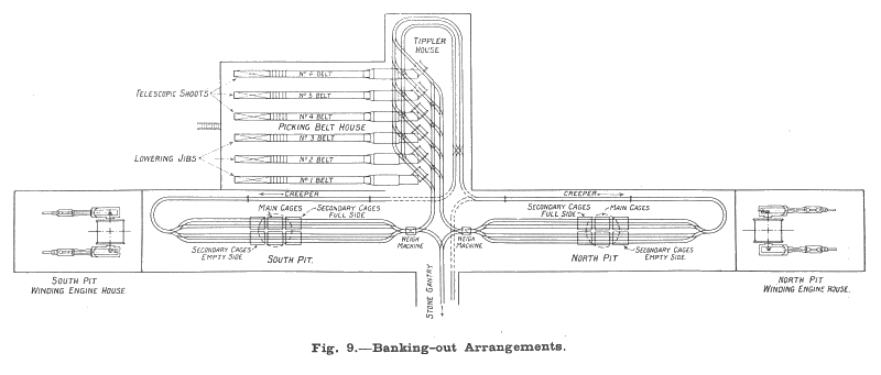
Fig. 9 shows the banking out arrangements, which particularly lend themselves to economy of labour. The full tubs from each pit gravitate from the cages, over the weigh machine to the tipplers, with a minimum of handling. After being emptied, they further gravitate to a point at the bottom of the creepers, from where they are automatically raised to a sufficient height to allow them to return without assistance to the hydraulic decking gear at the shaft.
Six automatic tipplers of the "Wood & Burnett" type made by the Grange Iron Company are employed to distribute the coal on to the shaking screens. The undersize coal, 0-1 5/8, is conveyed direct to the washery or to a storage bunker, from which it is drawn as required and conveyed to the washery by means of two Robbin's conveyors. Oversize coal, above 1 5/8 in., is delivered on to the picking belts, which are 4 ft. 6 in. wide and 60 ft. 6 in. long, excluding the jib ends. These belts travel at a speed of 45 ft. per minute, and do not essentially differ from the usual type of steel plate conveyors.
Waste stone from rippings in the Bord and Pillar workings is raised to the extent of 1,700 to 2,000 tons per week from the pit. After leaving the cage the tubs of stone gravitate to a gantry where a small endless rope haulage conveys them to the dump after being tipped, the empty tubs gravitate to the bottom of the creepers and so return to the pit.
The washery debris, belt debris, boiler ashes, &c., is dumped into wagons and taken to a reinforced concrete hopper having a capacity of 350 tons, from which it is transported to the sea by means of an aerial ropeway. This ropeway is of the hi-cable system, by R. White & Sons. It is 2,000 ft. in length and capable of dealing with 40 tons per hour, absorbing 15-h.p. Various views of this ropeway are shown on Figs. 17, 18 and 19, from which it will be seen that the tipping of the buckets is entirely automatic.
Washeries.
As already mentioned the "undersize" from the screens Is taken either direct to the washery or to a concrete hopper (the nearer of the two shown in Fig. 15), where it is stored until required. From here it is conveyed to the washery by two parallel Robbin conveyors. The washing equipment consist of two Baum units, of 40 tons per hour capacity each, by Simon Carves, Ltd. Three classes of coal are made, the sizing being clone by two compound cylindrical trommels, one of which is shown in Fig. 13. The undersize (5/8 in. to 0 in.) from the trommels is pulverised by two Carr's disintegrators, and is taken by means of an elevator to a 2,000-ton concrete hopper, where it is ready to supply the demands of the coking plant. Single nuts (1 in. to in.) and double nuts (1 in. to 1 5/8) in., comprise the other two classes, which are loaded into trucks.
Coke Ovens.
The plant consists of 120 Koppers regenerative coke ovens 60 of these ovens were built in 1916, and a further 60 have just been completed. Charging 16 ovens per shift in each battery, the dry coal utilised averages 864 tons per day total.
Coal is brought to the plant as mined, and the dirt is removed in the washer already described. It then passes to a crusher house, where the coal for the ovens is crushed to the required size. Two 130-h.p. totally enclosed motors are provided to drive the crusher. The coal is then elevated to a storage bunker of 2,000 tons capacity. From there the coal falls into an electrically-driven top charging machine travelling along the top of the ovens. Two of these machines are provided. The ovens are of the well known Koppers regenerative type, and need not be further described. They are 32 ft. 9 in. long, 8 ft. 6 in. high, and have a tapering width of from 19 in. to 21 in. When carbonised, the resulting coke is discharged from the oven by means of a ram and falls on to a coke bench of the usual design. Two discharging machines are provided for the full plant of 120 ovens, and one retained as a spare.
The gases evolved from the coal are led to the by-product plant by a gas main and thence pass to a tubular water cooler, where the temperature is reduced to about 200 C to 250 C. The greater part of the tar and water contained in the gases is deposited here and flows away to a large separating tank. The tar sinks to the bottom, and is drawn off into a tar storage tank, the ammonia liquor being run off the top into the ammonia liquor storage tank. The tar is not further treated, but is sold direct to the tar distillers. The liquor is separately treated in stills and the ammonia is volatilised and passed back into the main gas stream, as will be described later.
After leaving the coolers the gas passes through steam driven exhausters of the Bryan Donkin type. Three of these exhausters are provided, one being a standby. Each set is driven by a horizontal steam engine, 14 in. bore by 18-in stroke, and is capable of exhausting 270,000 cubic ft. of gas per hour against 4-in, vacuum and 52-in. w.g. pressure when running at a speed of 95 r.p.m. The engines are provided with expansion gear and drive the exhausters through universal couplings. The speed of the plant is governed by special regulators, which control the speed of the engine, acting on the steam supply to maintain an even pull in the hydraulic main of the ovens from which the plant is exhausting.
The exhausters are of the rotary positive design of the modern two-blade type. In this type of machine the shell is bored out oval to suit the motion of the slide, which rotates on a block, which in turn runs on a pin fixed in the back endplate on a centre corresponding to that of the shell. In this shell, on a centre below that of the shell, an axle rotates. A slide passes through this axle and sweeps out, twice per revolution of the axle, the crescent-shaped space between the axle and the shell. A view of the exhauster house is shown in Fig. 16.
Following the exhauster the gas passes through a tar extractor in order to remove the tar fog, which is always obstinately retained by the cooled gas. The gas is then heated up again to 650 C. by means of exhaust steam and passes into the saturator, where the ammonia is recovered by sulphuric acid. Just before the gas enters the saturator the ammonia which has been driven off from the liquor by distillation is passed into the gas stream. The whole of the plant in the sulphate house is duplicated. Rotary sulphate drying neutralising plants of the company s own design are installed in the sulphate house for the manufacture of neutral dry sulphate of ammonia.
After passing the saturator the gas is cooled down for recovery of benzol by passing through each of three coolers, where the gas flows in counter-current to the water. It then flows up each of four benzol scrubbers arranged in series, the benzol being removed from the gas by a stream of creosote oil which flows down the scrubbers. The benzol-free gas is then passed into a gasholder, after which a proportion of it is used for heating the ovens. About 40 per cent, of the gas is required for this purpose, the remainder being available as surplus.
A complete benzol plant designed in accordance with the latest Koppers practice is installed, wherein the benzolised creosote oil is subjected to distillation and 65 per cent. benzol is manufactured, Fig. 14 shows a general view of the chemical side of the plant.
Surplus gas is normally passed to the boiler furnaces of the adjoining Waste Heat Company's power house, to which further reference will be made.
Electrical Arrangements.
Numerous advantages accrue from the very close co-operation which has been established between the Colliery Company and the Cleveland and Durham Electrical Supply Co. Ltd., through the interposition of the Waste Heat Co. Ltd. Surplus gas from the coke ovens is passed over to the latter's power station adjoining the colliery, and is burnt under Babcock & Wilcox water-tube boilers, the steam from which operates two 3,000-kw. turbo-alternators. These work in parallel with the Supply Company's system, as also does a 1,000-kw. low-pressure turbine utilising the exhaust steam from the main winding engines, air compressors and other auxiliary plant. The Colliery Company buys back an equivalent amount of energy to that thus developed, at a very low rate per unit, but excess requirements are met from the Supply Company's system at a higher rate of payment. One consequence of this mutual system of working is that, having generators practically on the spot, there is no urgent necessity to ensure power factor regulation within close limits, since there are no long supply cables involved. Hence induction motors are employed extensively in both large and small sizes.
Again, all exhaust steam can be advantageously and economically utilised by means of the low-pressure set seen in Fig. 21. This is a Richardson, Westgarth & Company's turbine running at 2,400 r.p.m. and coupled to a Siemens three-phase 3,000-volt alternator: it uses steam at about 3 lb. per square in., supplied from a Morison accumulator, approximately 25 ft. in length by 6 ft. 6 in. in diameter, into which the various engine exhausts are led. A Westinghouse jet condenser provides a vacuum for the turbine, and its extractor pump, driven by a 128-h.p. motor, also lifts the injection water and condensate to the top of a Premier cooling tower. A Reyrolle compound-filled switchboard controls the output of this set and a number of 3,000-volt distributing cables.
When Horden Colliery equipment was first designed direct current was utilised to a considerable extent. It is still employed for surface lighting and for small surface motors, which are supplied by means of the rotary converters seen in Fig. 23. These are 400-kw. Siemens machines, two of which deliver 500 volts for power work and the remaining two supply 220 volts for lighting. Their transformers take energy at 3,000 volts, three-phase, 40 cycles.
For underground lighting a separate transformer is installed in each seam, reducing the voltage from 3,000 to 110 volts, AC. all lighting cables are wire-armoured, with suitable fittings.
Air Compressors.
Compressed air for use underground is supplied from the main power house, which contains four Belliss & Morcom two-crank two-stage vertical steam-driven compressors, each having a capacity of 3,000 cubic ft. of free air per minute, delivered at 100 lb. per square in. The steam cylinders are 23 and 33 in. in diameter, with 15-in, stroke, developing 595 i.h.p. at 240 r.p.m., and air cylinders are 19 and 33 in. in diameter. Forced lubrication is used, as is standard practice with these sets.
To convey the air underground a single 12-in. Mannesmann weldless steel main is used in the shaft, and branches are taken from this to all seams. Air receivers are placed at the shaft bottom ; also in-bye receivers are provided, the air being conveyed underground by means of 9-in. diameter steel mains.
Acknowledgments.
We have to express our thanks to Mr. J. J. Prest, the Agent of Horden's Collieries Ltd., for his permission to visit Horden Colliery, to take photographs, and to prepare this article for publication. The Chief Engineer of the company, Mr. A. E. Charlesworth, gave us great assistance in the collection of data and in arranging facilities for the photographs. A feature which particularly impressed us in connection with the equipment of this colliery was the extent to which the staff's own designs were utilised. The Chief Engineer was undoubtedly justified in attributing much of the steadiness with which the whole plant operated to the fact that each part had been carefully co-ordinated with the others in order to perform its work reliably and thoroughly.
Drawings and Photographs accompanying the article


Article reproduced from a copy of the magazine held at National Mining Museum Scotland, Newtongrange, Midlothian.




 Contains public sector information licensed under the

