


 |

|

|

| |
 |
 |
|||

April, 1924
The Horden Colliery
Drawings and Photographs accompanying the article
| Sample | Description |
|---|---|
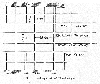 | Fig. 1 — Lay-out of Roadways |
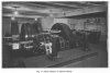 | Fig. 2 — Main Hauler in Hutton Seam |
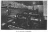 | Fig. 3 — Pump Room in Hutton Seam |
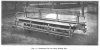 | Fig. 4 — Jaunting Car for Men Riding Set |
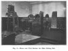 | Fig. 5 — Main and Tail Hauler for Men Riding Set |
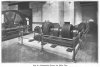 | Fig. 6 — Alternative Drives for Main Fan |
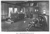 | Fig. 7 — Main Winding Engine at East Pit |
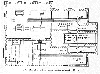 | Fig. 8 — Plan of Main Fan House, Showing Alternative Drives |
 | Fig. 9 — Banking-out Arrangements |
 | Fig. 10 — Headgear and Superstructure of East Pit |
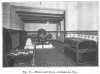 | Fig. 11 — Motor and Drive of Stand-by Fan |
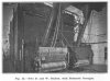 | Fig. 12 — Two B. and W. Boilers, with Balanced Draught |
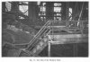 | Fig. 13 — One Unit of the Washery Plant |
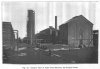 | Fig. 14 — General View of Coke Oven Recovery By-Product Plant |
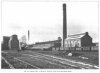 | Fig. 15 — General View of Washery, Bunkers, Coke Ovens and Boiler House |
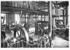 | Fig. 16 — Interior of Exhauster House for Coke Ovens and Chemical Plant |
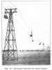 | Fig. 17 — Overhead Conveyor for Stone Refuse |
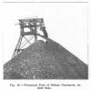 | Fig. 18 — Terminal Pole of Refuse Conveyor, on Cliff Side |
 | Fig. 19 — Driving and Charging Gear of Refuse Conveyor |
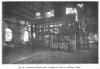 | Fig. 20 — Hydraulic Decking Gear, showing full Tubs in Auxillary Cages |
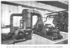 | Fig. 21 — 1,000 k.w. Turbo-Alternator and Condenser using Exhasut Steam from Accumulator |
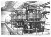 | Fig. 22 — Four Steam-driven Air Compressors, each 3,000 lb. per min. of free air capacity delivered at 100 lb. per sq. in. |
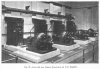 | Fig. 23 — Four 400 k.w. Rotary Converters for D.C. Supplies |
Article reproduced from a copy of the magazine held at National Mining Museum Scotland, Newtongrange, Midlothian.




 Contains public sector information licensed under the

