


 |

|

|

|
|
 |
 |
|||

April, 1924
THE HORDEN COLLIERY
An Illustrated Account of the Equipment of a Colliery Winding over 4,000 tons of Coal per Diem.
Of the 3,000 odd collieries in Great Britain, there must be comparatively few that reach the output regularly attained by the Horden Colliery, Co. Durham, and still fewer whose tonnage approaches the figure anticipated by the end of the year. At present an average of 4,000 tons a day is being raised from two shafts, whilst on occasions an output of 4,400 tons has been obtained; and even this does not represent the ultimate capacity of the present equipment, which is designed to bring to bank 400 tons of coal per hour. A third shaft — the East — is now used solely for winding men, but it is intended shortly to utilise this for coal drawing from the Main Coal seam, and by this means the average output of the colliery is expected to reach 5,500 tons a day.
Horden Sinking.
The coal measures in this portion of the Durham coalfield are overlain by Permian strata, and the history of the former sinkings through these made it certain that large volumes of salt water would be encountered in the gullets of the magnesian limestone, while the quantity of water found in the sand-bed below the limestone might similarly be expected to be excessive. In view of this knowledge it was decided to put down temporary sinking plant with pumps capable of lifting 12,000 g.p.m. from a depth of 140 yards to the surface. Advantage was taken of the proximity of the site to the high sea cliff and a delivery drift, 6 ft. by 6 ft., or sufficiently large to pass the total quantity delivered by the pumps, was cut from the pits to the sea. The delivery end of the drift was kept 6 ft. above the level of the spring tides, and there was a difference of 210 ft. between the top of the pits and normal high-water level.
The successful sinking of the three pits through this difficult ground has been attributed by Mr. H. S. Childe to Mr. J. J. Prest's boldness in using eight sets of pumps, each 30 in. in diameter. A separate pump engine was employed to drive each of the pumps independently, the pumps being hung in pairs so as to balance each other. Considerable difficulty was encountered in keeping the buckets and clacks in good working order, owing to the erosion caused by the sandy water.
Sinking operations were conducted simultaneously in all three pits, though necessarily intermittently in any one of them, due to the difficulties encountered. The North shaft was completed in 45 months; feeders of water up to a maximum of 9,230 g.p.m. were tapped and successfully dealt with.
The East pit proved to be the most difficult sinking of the three, despite the fact that bore holes were sunk from it to an under-level drift, connected to the other two pits, in order to drain the water. The difficulty was owing to the number and direction of the joint planes, and a greater thickness of soft sand as compared with that encountered by the other shafts. The time occupied in sinking and tubbing the shaft from a depth of 152½ yards down to 178 yards, was actually 27 weeks. Eventually, ordinary wooden piling was employed, the shaft being increased to 28 ft. in diameter for the purpose. By this means it was sunk 20 ft. into the sand, but then collapsed and carried large quantities of sand into the South pit sump, partly filling the latter and the under level drift with sand, which, in turn, caused the pumps to break down from time to time. The shaft was thus filled with debris until the bottom was brought within 12 ft. of the last wedging curb. After again being sheared back to 28 ft. diameter, several hundred tons of concrete in bags was packed closely behind the timber, as it was found that the total mass began to descend as the sinking progressed. Five tiers of piles employed in this manner — workmen being continually employed in filling and stowing bags of concrete behind the top of the anchoring timber as the mass descended — eventually carried the sinking down to the coal measures at a depth of 172 yards.
Shafts.
The following are the depths of the various seams below the surface :—
| ft. | ||
| Surface to | Five-Quarter seam | 800 |
| " " | Main Coal seam | 860 |
| " " | Low Main seam | 1,080 |
| " " | Hutton seam | 1,200 |
For a depth of about 186 ft. from the surface, the shafts are lined with brick walling of an average thickness of 18 in.; below this, the shafts are lined with cast-iron tubbing to a depth of 92 fathoms below the surface, the remainder of the lining being brick walling 14 in. thick.
The two main shafts each have a diameter of 20 ft.; the North forms the outlet for the Hutton coal and the South deals with the output wound from the Low Main seam. Both of these are downcast. The East pit, 17 ft. in diameter, serves as the upcast.
The cages in the larger shafts are double-decked and are provided with double sets of rails to take two tubs abreast, each cage thus holding eight tubs. Their dimensions are 7 ft. 8 in. by 9 ft., and the centres are 8 ft. 9 in. apart. "Reliance" sockets are used to secure the cage chains to the winding ropes, which are 6 in. in circumference.
Rope guides of the lock coil pattern, having a diameter of 1½ in. are hung at the four corners of each cage and two 2-in, rubbing ropes composed of solid ½-in. rods are provided to ensure further against accidents.
Roadways.
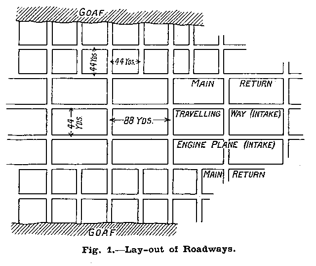
The layout of the roadways is on a necessarily large scale and represents the best modern practice in having two main intakes and returns. A sketch plan of the roadways with their supporting pillars is shown in Fig. 1. Their dimensions are interesting. The main engine plane, which necessarily serves as an intake airway, has a width of 12 ft. and averages 10 ft. in height; the travelling way for the men is 8 ft. wide and has an average height of about 7 ft. In both cases the roof is supported by girders, which rest on brick walls 2 ft. in thickness. The two return airways each have a width of 10 ft. and are 9 ft. high.
System of Haulage.
In the Hutton seam, the haulage system on the main engine plane is of the endless rope type, the speed of the tubs, which run in sets of five, being 2 miles an hour. Two haulages are installed in tandem, in a common engine house. The larger of the two is by The Grange Iron Co., and is fitted with two fleeting wheels 8 ft. in diameter ; this haulage is driven by means of a 300-h.p. motor by The Metropolitan-Vickers Electrical Co., Ltd., working on an alternating current, 3-phase, 3,000-volt system, at a speed of 390 r.p.m. This motor is controlled by means of a Metro-Vickers liquid type reversing controller with oil-immersed reversing switches. The other haulage is by Messrs. M. B. Wild & Co., and is fitted with two fleeting wheels 6 ft. diameter, and driven by means of a 100-h.p. motor.
Each haulage wheel operates a separate district of the pit and may be stopped separately when required by means of a hand wheel, seen in the foreground of Fig. 2, which disengages a friction clutch and applies a band brake. The engine planes are laid with 40-lb. section rails and the haulage ropes are 1-in, diameter. The Low Main seam is equipped in a similar manner to the Hutton seam.
Auxiliary main and tail haulages, worked by compressed air, and ranging from 10 h.p. to 80 h.p., keep the main system supplied with coal. Tubs of tried design, substantially built of steel sheeting on oak trains, are used throughout; they have a tare of 6½ cwts. and carry 11 cwts. of coal.
Travelling Arrangements.
When it is remembered that the total distance from the shaft to the face is over 3,000 yards, it will be appreciated that, were the men to walk, a considerable proportion of their shift would be occupied in travelling. A main and tail haulage has, therefore, been installed to ride the men to and from their work. At the moment, the total travelling distance of the set is 1,860 yards, but eventually it will be extended to 3,000 yards, and this without alteration to the existing driving gear. Ten miles per hour is attained by the jaunting cars, which are exceedingly well-sprung and fitted with roller gearings the travelling is remarkably smooth. Fig. 4 shows one of these cars at bank.
The gauge is 2 ft. 9 in. and the permanent way is laid with rails of 45-lb. section. The set consists of 20 cars, each riding 12 men; all cars are connected by solid links and a safety chain runs the full length of the set. In the event of broken ropes, brakes can be operated by the setrider, who can also communicate with the engineman and stop the set at any time by short-circuiting two overhead bare wires with a copper fork.
A 300-h.p. Metropolitan-Vickers induction motor drives the hauler. An ingenious overwinding device, designed by the engineering staff, is incorporated with the brake gear. It comprises a nut travelling along a screw which is chain driven from the main drum ; at its extreme travel the nut makes electrical contacts, short-circuiting a solenoid which normally holds the brake weights off, and opening the motor circuit breaker. The mechanical parts of this hauler were supplied by the Grange Iron Company, Ltd., and the four band-brakes have Ferodo linings.
Methods of Working.
Two seams — the Hutton and the Low Main — are at present being worked, whilst a third, the Main Coal, is being opened out. The main output is obtained from the first of these seams, which is 5 ft. in thickness and occurs at a depth of 200 fathoms.
Both the Longwall and Bord and Pillar methods are in use in winning the coal. In the Longwall workings the gateways are 29 yards in width and the coal is removed by sumping in the centre and taking off lifts in opposite directions or, when coal cutters are used, the faces are kept about 350 yards in length, and the cutting done by air driven Diamond & Jeffery machines, the chain type being favoured in each case. On an average, the depth of cut is 4 ft. 6 in., and where circumstances permit, as in the Low Main East districts, the cut is made in the stone and inferior coal.
In the Bord and Pillar districts, the coal is all hand-won, excepting in the Low Main Straight South district, where the coal is very hard, and all winning work is done by means of Hardiax heading machines.
The bords are 5 yards in width, and the headings 4 yards. Pillars are cut 44 yards square and the broken workings conducted on the advancing system, follow closely behind whole operations before the bords have time to fall.
Pumping Plant.
The amount of water made in the workings cannot said to be excessive, a fact which is remarkable when enormous quantities encountered in the Yellow Sa??? during sinking operations are considered. Ample provision is made to meet a very substantial increase in the present quantity raised, in the pumping installation. Two separate sets are provided — a seven-stage turbine pump Mather & Platt, Ltd., with a capacity of 350 g.p.m.. forming the main unit. In reserve there is a three-throw r. pump by Frank Pearn & Co., Ltd., with a capacity 200 g.p.m.; this is belt-driven by an 80-h.p. Metropolitan Vickers three-phase induction motor. The pressure head against which these pumps work is 470 lb. per square inch.
Sufficient water to supply the requirements of the colliery boilers, coke ovens and for general use is collected from the tubbing in the shafts. It is brought to a standage in the Five Quarter seam and raised to the surface at the rate of about 500 gallons per minute.
Ventilation.
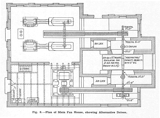
A Walker fan of the "Indestructible" type, running at 125 r.p.m., and having a capacity of 257,000 cub. ft. against a 4-in, water gauge, forms the main ventilation unit of the colliery. Power is normally supplied by a Metropolitan - Vickers induction motor through a rope-drive, but in the case of an electrical breakdown, the fan can be coupled to a cross compound non - condensing Walker engine, with cylinders 21 in. by 37½ in. by 42 in. Details of this arrangement are seen in Figs. 6 and 8, the latter of them giving a plan of the arrangements and the former a general view. Although the motor is rated at 350 b.h.p. only 270 b.h.p. are required for present requirements. There is thus a considerable reserve of power for future developments.
To ensure perfect immunity from breakdowns, a Sirocco fan, 7 ft. diameter, 6 ft. wide, and having a capacity of 230,000 cub. ft., against a 3-in, water gauge is provided as a standby. This is driven by a 250-h.p. Siemens motor running at 390 r.p.m. A general view of the motor, with liquid stater and rope drive, is seen in Fig. 11.
Drawings and Photographs accompanying the article


Article reproduced from a copy of the magazine held at National Mining Museum Scotland, Newtongrange, Midlothian.




 Contains public sector information licensed under the

