


Mail: Webmaster

|

|

|

|
|
 |
 |
|||
Chapter III
The appliances used when withdrawing supports
 The devices most frequently used in the withdrawal of the supports are the sylvester and the monkey winch.
The Sylvester
A description of the sylvester was given in Training Manual No. 1 and readers are referred to this.
A sylvester fitted with two gears is found to be an advantage when removing roadway supports. The box of the sylvester is so designed that it carries two pawls (Figure 24). In the high gear only one of the pawls is effective and this operates when the lever is moved through an angle of 54° In the low gear, both pawls are effective, and one operates when the lever is moved through an angle of 45° and the second when the lever is moved through a further angle of 45° The advantage of this second gear is that it allows a relief of effort and a probable change of position before the second pull is taken.
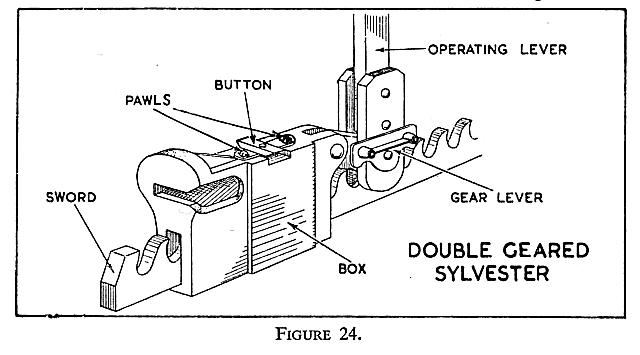
The gears are changed by means of the attachment at the base of the sylvester lever.
The Monkey Winch
The winch is a device used for exerting a strong pull and is used underground in some mines to withdraw girders from disused roadways. It is most suitable for this work since the length of the pulling rope is such that the winch can be set up in a safe area well away from the position from which the supports are to be withdrawn. As shown in Figure 25, the winch consists of a framework containing a drum, round which a rope 50 feet in length is wound. The drum may be turned by operating a lever placed on an extension of the drum spindle, shown in the Figure 25 as the fast speed square. Another means of turning the drum is by placing the lever on the power square. From this position the drum is turned through simple gearing. To hold the drum in position a ratchet device is used with both gears. A simple reversing mechanism which disengages the ratchet is also attached.
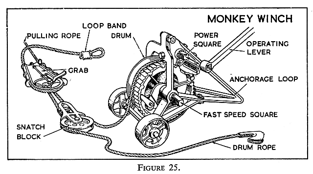
To enable objects to be reached at a greater distance than the drum rope will reach, a 40 foot pulling rope is provided. To connect the pulling rope and the drum rope, a grab and a snatch block are provided. The grab is clamped to the pulling rope and the drum rope may be attached to it directly or indirectly by the snatch block, as shown in Figure 25.
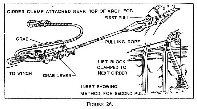
To enable the rope to be fastened to the girders, a girder clamp is provided (Figure 26) and should the girder have penetrated the floor, a small lift block is also provided as shown in Figure 26.
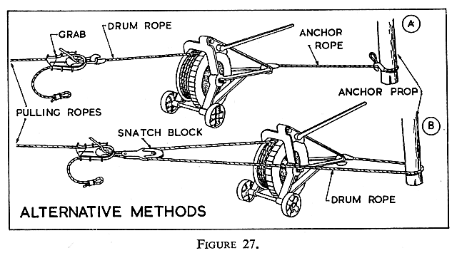
The winch may be anchored in two ways, directly from the anchor loop of the framework by a 15 foot anchor rope to the anchor prop (Figure 27A), or as shown in Figure 27B with the drum rope passed round the snatch block and the anchor prop, and with the hook attached to the anchor loop of the framework. The advantage of this second method is that the pulling power of the machine is doubled. This method should be used when pulling out heavily loaded girders.
Do not anchor the winch to any roof support and always point the winch in the direction of the pull so that the rope will wind correctly on to the drum. When setting up the winch, ensure that the vertical angle of pull is as small as possible. To do this, keep the winch as far away as possible from the support to be withdrawn. If this is not done the winch will tend to lift off the ground and so make the work difficult.


 |
 |
 |
||

Back |

Home |
Copyright © 1999-2012 by The Durham Mining Museum and its contributors
Page last updated: 01 Jan 2008 |

Search |

|