


Mail: Webmaster

|

|

|

|
|
 |
 |
|||
Chapter II
The Setting of Roadway Supports
 Before commencing any of the operations set out below examine the place to see that it is safe.
The Setting of Breaking Off Props
| Materials and Tools required: | |
| Props (wood or steel). | |
| Lids. | |
| Hammer (5 lbs. to 7 lbs. in weight). | |
| Pick. | |
| Saw and hatchet (where wood props are used). | |
| Chalk and string. | |
1. On each side of the roadway, mark a breaking off line on the roof. This is done by marking points on the roof at distances from the centre line equal to half the total width of the roadway and joining the points together by a line.
2. Set a row of props with the front of the prop immediately behind the breaking off line, as shown in Figure 10. The props should be set firmly on the floor and tight against the roof.
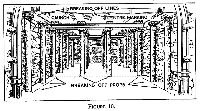
3. Set extra props and lids under the carrying girders to prevent the rocks being broken too far in advance.
Setting of Forepoling Girders
| Materials and Tools required: | |
| Two girders. | |
| Three sets of girder clamps. | |
| Covering materials. | |
| Wedge lids. | |
| Hammer. | |
| Spanner. | |
1. Attach the girder clamps to the roadway supports as shown in Figure 11.
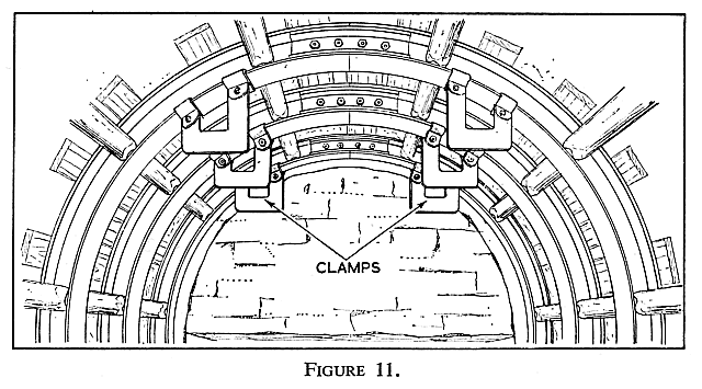
2. Slide the two girders through the clamps, one on each side of the roadway.
| Note: |
The two girders should extend in advance of the roadway supports.
|
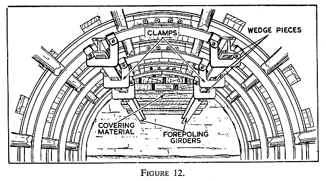
3. Drive wedge lids between the girders and the clamps to fix the girders in position.
4. Secure any exposed roof by wood pieces as shown in Figure 12.
TO ADVANCE THE GIRDERS
1. Remove the covering materials from above the girders and the wedges from the two girder clamps furthest from the ripping.
2. Remove these two clamps and reset them on the arch girder nearest to the ripping so that they hold up the forepoling.
3. Remove the wedges from the other clamps and slide the girders forward to the ripping. Tighten them in their new positions with the wedges set between the clamps. Secure the roof above the girders with covering material.
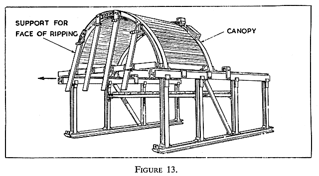
A gatehead canopy is shown in Figure 13. When the shots have been fired the canopy is free to move forward on the lower structure and from it the roof and slides of the newly exposed part of the roadway and the face of the ripping can be secured.
The Building of a Gate Side Pack
| Materials and Tools required: | |
| Shovel. | |
| Hammer. | |
| Pick. | |
| Steel wedges (if required, for breaking large pieces of stone). | |
| Sylvester. | |
| Chalk and string. | |
1. Examine the area to be packed.
2. On the roof, draw a line to which the outer walls are to be built.
| Note: |
Better results are obtained if packs are built in sections. By this method the material is kept tight within the pack, and the cross walls increase the strength of the pack. When the pack is built in sections, fewer supports are likely to be removed at a time.
|
3. Clean up the floor for the foundation stones of the pack walls of the section furthest from the roadway. Lay the stones with their lengths pointing into the pack. Throw in small dirt to the level of the top of the foundation stones.
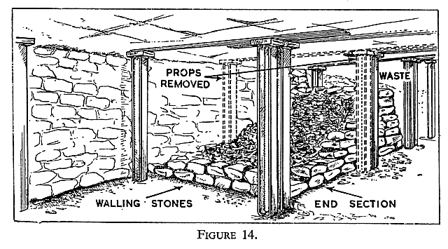
4. Spread the small dirt on top of the foundation stones to act as 'bedding or mortar' for the next layer of wall stones. Put on the next layer of wall stones crossing the joints of those below. Fill in with loose dirt allowing some to act as bedding for the next layer of walling stones (Figure 14). Continue this until the section is built to the roof.
| Note: |
The debris must be rammed tightly to the roof before the walls of the pack are completed, so that the pack as a whole and not only the walls support the roof.
|
5. Set temporary props and remove the supports to enable the next section of the pack to be built.
6. Build up the remaining sections as described in operations 3 and 4.
| Note: |
In level or nearly level seams it is good practice to slope the outer walls of the pack inwards towards the top about 1” for every foot in height. This reduces the likelihood of the walls bulging outwards and collapsing under pressure. The amount of slope, if any, in inclined seams depends upon local conditions.
|
The Setting of Supports to the Face of the Ripping
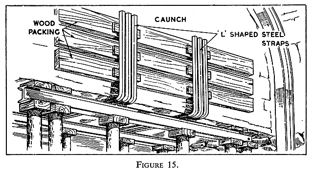
There are various types of supports. The type described here consists of 'L' shaped steel straps set over the caunch girders.
1. Slide the 'L' bars over the caunch girders—one on each side of the roadway.
2. Insert wedges between the girders and the bars. Drive in the wedges to secure the bars to the edge of the ripping.
| Note: |
The upright portions of the bars should be in such a position as to allow packing pieces to be placed between them and the ripping.
|
3. Place wood packing pieces between the upright of the 'L' bars and the face of the ripping. Secure them firmly in position (Figure 15).
| Note: |
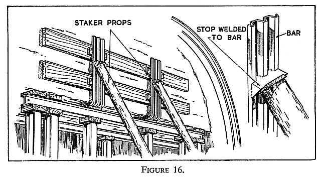
Welded to the upright portions of the 'L' bars there may be brackets to which staker props or sprags may be set to give extra support (Figure 16).
|
Setting a Girder
Always see that sufficient manpower is available to handle a girder. Accidents may be caused by lack of sufficient men when raising or lowering a girder.
A. STRAIGHT GIRDER ON WOOD PROPS
| Materials and Tools required: | |
| Girder. | |
| Two wood props of suitable length. | |
| Struts—wood or metal. | |
| Lids and wedges. | |
| Pick. | |
| Shovel. | |
| Hammer. | |
| Saw. | |
| Chalk and string. | |
1. Mark on the roof the centre line of the roadway and mark the centre of the girder.
2. Square off the sides of the roadway and remove any debris from the position in which the girder is to be set. Make the floor level where the feet of the props are to be placed.
3. Erect a platform or scaffold if the height of the roadway is such that the girder cannot be raised into position when standing on the floor.
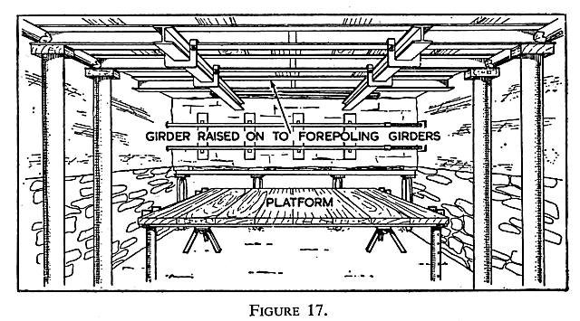
4. Raise the girder on top of the forepoling girders (Figure 17).
| Note: |
The centre of the girder should be under the centre line marked on the roof.
|
5. Measure the two props and saw them to size if necessary, so that with the lid placed between them and the girder they will set the girder and covering materials tightly to the roof.
6. Ensure that the girder is placed at the correct distance from the girder previously set and that it is placed at 90° to the centre line. This can be done by varying the lengths of the struts inserted between the girders.
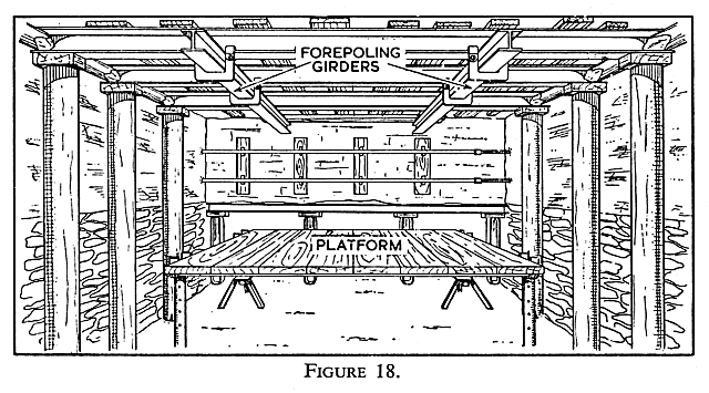
7. Set the props one under each end of the girder. Place lids between the tops of the props and the girder. Drive the props into position, fixing the girder and the covering material tightly to the roof (Figure 18). Pack any cavity above the girder with wood pieces.
| Note: (a) |
At junctions, loading places and elsewhere in a mine it has become common practice to secure several of the roadway girders with carrying girders or 'runners'. Each end of the runner must be supported by at least two props or, preferably, by chocks.
|
|
| (b) |
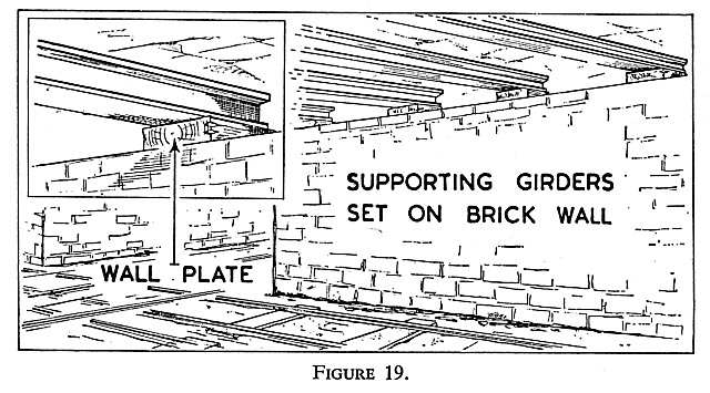
At these points the girders are often set in brickwalls and are held to the roof by jack props set firmly on the floor and placed a short distance from each end of the girder whilst the walls are built. When completed, pieces of wood (wall plates or pads) are inserted between the girder and the top of the walls (Figure 19). These wall plates wedge the girder tightly to the roof and also act as crushing pieces should the girder become heavily loaded, so protecting the wall from damage. They also help to spread the load over a wider area of the wall.
|
|
| (c) |
Jack props are frequently used to support a girder around which repair work is being carried out.
|
B. CAMBERED GIRDERS
| Materials and Tools required: | |
| Cambered girder. | |
| Hammer. | |
| Pick. | |
| Wedges. | |
| Covering materials. | |
| Struts. | |
| Chalk and string. | |
1. Mark on the roof the centre line of the roadway and also mark the centre of the girder.
2. Square off the sides and, if required, erect a platform or scaffold.
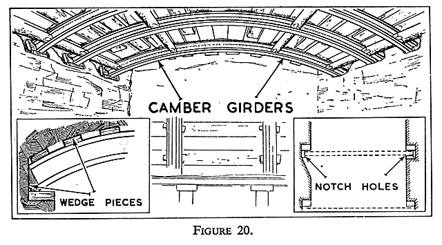
3. Cut notch holes in the sides of the roadway (Figure 20).
| Note: (a) |
The position of the hole to be cut is usually marked off a strut length from the girder previously set. This distance should conform to the Colliery Support Rules.
|
|
| (b) |
It is usual to cut one of the holes deep enough to take a lid behind the end of the girder.
|
|
| (c) |
The hole at the other side of the roadway is usually made in such a way that the girder can be slotted into it.
|
4. Raise the girder on to the forepoling girders, and place the centre of the girder under the centre line marked on the roof.
5. Place the girder into the first notch hole (paragraph 3, note b). A wood lid should be placed between the end of the girder and the back of the hole. The end of the girder should also rest on a wood lid.
6. Slot the other end of the girder into the notch hole at the other side of the roadway. Lids should be placed behind and under the girder end.
7. Place struts between the flanges of the new girder and the one previously set. Place covering materials between the girder and the roof and fill in any cavity above the girder with wood pieces.
8. Drive in wedge lids to fix the girder firmly in position and tightly against the roof (Figure 20).
C. ARCH GIRDERS
| Materials and Tools required: | |
| Two halves of the arch. | |
| Two fishplates. | |
| Nuts and bolts (two or four as required). | |
| Two spanners. | |
| Hammer. | |
| Pick. | |
| Shovel. | |
| Covering material. | |
| Wedge lids. | |
| Footpieces and stilts. | |
| Struts. | |
| Chalk and string. | |
1. Erect a platform or scaffold.
2. Mark the centre line of the roadway on the roof. Trim the sides of the roadway.
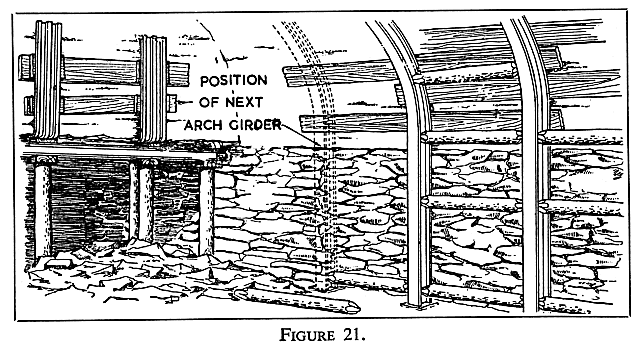
3. Fix the positions where the feet of the next arch will be placed by measuring a strut length from the bottom of the arch previously set (Figure 21). Remove any debris from these positions and make the floor level.
4. Place the footpieces in position.
| Note: |
To ensure that the arch will be set squarely in the roadway it may be necessary to build up the footpieces. Use a levelling line and see that the footpieces are built to a horizontal line across the roadway.
|
5. Raise one half of the arch into position on one side of the roadway with the foot of the arch resting on the footpiece. Where possible rest the first half of the arch against the forepoling girders to take the weight whilst the second half is being placed into position. Specially designed clamps or struts may be fitted between the arch previously set and the new section to hold it in position until the work is completed.
| Note: |
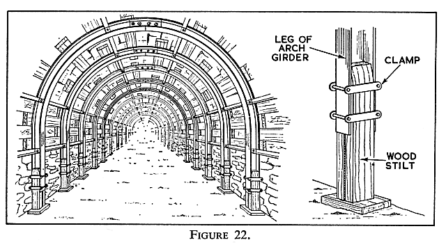
Where convergence is great, stilts should be attached to the arch (Figure 22).
|
6. Place the second half in a similar position at the other side of the roadway.
7. Bolt the halves together. The joint should be directly under the centre line marked on the roof.
| Note: |
The bolts should be inserted through the fishplates and the girder from the inbye or face side. All bolts should be used and the nuts tightened as much as possible.
|
8. Insert struts between the newly set arch and the one previously set. The struts shouid always be set to given lines since this helps to prevent the arch buckling sideways when under pressure.
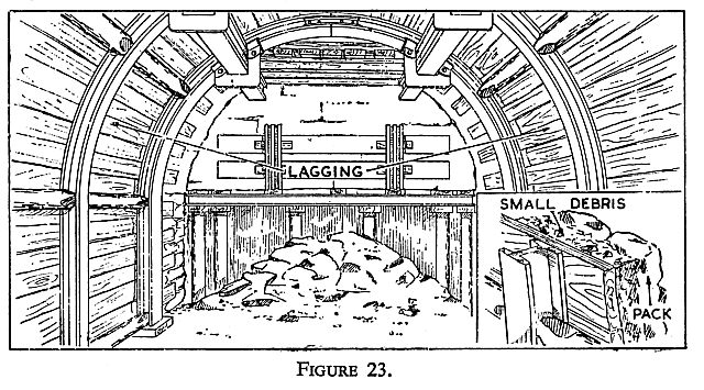
9. Secure the roof with covering material placed above the arch (Figure 23).
| Note: (a) |
The sides of the roadway should be secured by placing lagging material behind the legs of the arch and packing the space between the lagging and the sides with small pieces of debris. By doing this, distribution of the load is ensured over the whole of the roadway.
|
|
| (b) |
Where stilts are used it is necessary to examine them periodically after setting to make sure they are functioning correctly. The bolts holding the stilts should have an even tension. A specially designed spanner which slips at a predetermined tension should be used to ensure that all the bolts are of the same tension which would allow the stilt to slip, as the weight came on, before the girder buckled.
|
|
| (c) |
Where a three piece arch is used, it is set in a similar manner. The side pieces are placed in position and then the top piece is lifted into place and bolted to the side pieces. The centre of the top piece should be under the centre line of the roadway. Secure the roof and sides from the arch as indicated above.
|


 |
 |
 |
||

Back |

Home |
Copyright © 1999-2012 by The Durham Mining Museum and its contributors
Page last updated: 01 Jan 2008 |

Search |

|