


Mail: Webmaster

|

|

|

|
|
 |
 |
|||
Chapter I
General Description
Mine Roadways
 Roadways should be of ample size and should be maintained in good condition so that men and materials may pass along them easily, and so that a sufficient quantity of air may be circulated through the mine to ensure safe and comfortable working conditions for the men.
Most of the underground roadways in the mines of Great Britain are made immediately behind the coal face of longwall workings. They are as a rule made either by excavating the rocks of the floor or by ripping down the rocks of the roof until the required height is obtained. The material which is removed is then packed on each side of the roadway to act as pillars supporting the roof in that area.
Roadways may also be driven through the solid rock or through the goaf or waste of old workings. In these cases the rock is taken either out of the mine or to another part of the mine to be disposed of.
Movement of the Roof, Floor and Sides of Roadways
When a coal seam is extracted the roof lowers and sometimes the floor lifts so that there is 'convergence' between the roof and floor, with consequent loss of height. Account has to be taken of this in setting supports, especially in those roads that are immediately behind the coalfaces of longwall workings.
The rate of convergence depends a great deal upon the efficiency with which the packs are built at the coalface and along the sides of the roadways.
There is not only loss of height in roadways. The pressure of the roof causes the sides of the roadways to squeeze in and there is thus loss of width as well. Loss of width is much more pronounced where the rocks directly above the coal consist of soft shale than where they are of hard sandstone.
Loss of height and width are important factors which Colliery Managers have to keep in mind in deciding on the form of support that should be erected in the roadways, and it is important that the workmen should also keep them in mind when they are setting the supports.
Description of Supports
ARCH GIRDERS
In the mines of Great Britain the arch girder is the type most frequently in use to secure the roof and sides of underground roadways. As a rule it is made from normal H section girders bent to shape, and consists of halves bolted together by bolts and two fishplates as shown in Figure 1.
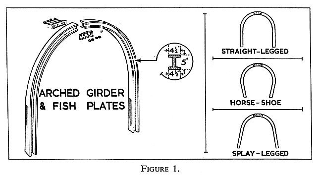
Arch girders are strong supports which have the additional advantages that they continue to provide support and are not readily dislodged even when they have been distorted by pressure from the rocks. They also give support to the sides of the roadway, and this is of great value when the sides are weak.
Arch girders are usually splay legged or straight legged in shape but horseshoe shapes are also in use.
The strength of the arch depends on the dimensions of the section of the girder and on its shape. The dimensions shown in the inset of Figure 1 are those of arches most commonly used.
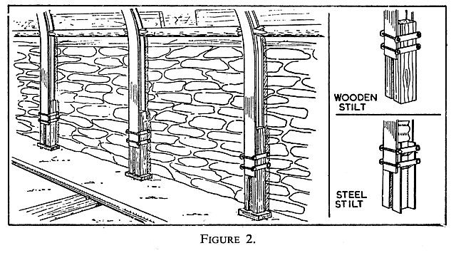
In many roadways, especially where there is a considerable amount of convergence, 'stilts' are attached to the legs of the arches (Figure 2). The stilts allow the legs of the arches to be forced down by the pressure of the rocks without damage to the arch itself. When the legs of the arches have been pushed down to the floor the stilts can be removed.
CAMBERED GIRDERS
As shown in Figure 3 these girders are slightly bent H section girders. As with arches, different sizes of girder sections are employed. A girder of the dimensions indicated weighs about 18-20 lbs. per foot.
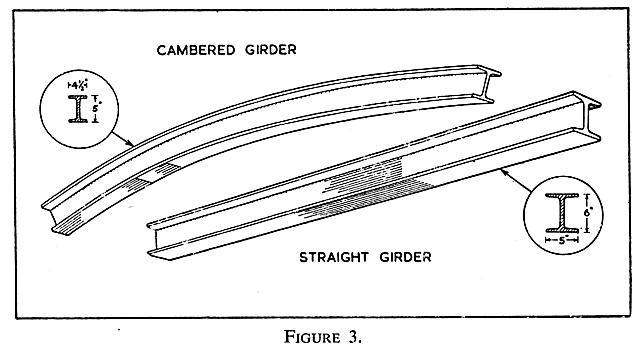
Cambered girders are used as roadway supports where the rocks forming the sides are strong enough for the girders to be supported on the sides of the roadway instead of on props. In some cases cambered girders set on brick walls have been used to support the roof.
STRAIGHT GIRDERS
H section girders are frequently used as roadway supports but channel section girders are used in special cases. The dimensions of a girder commonly used are 6” in depth by 5” width of flange (Figure 3). The girder may be supported by wood or steel props or by brick walls, the roof being made secure by covering materials placed over the girders.
FOREPOLING GIRDERS OR HORSEHEADS
These girders are used so that any roof that is exposed in advance of the permanent roadway supports can be made secure. They consist of two girders which are slung, one on each side of the roadway, from the permanent supports. The roof is then secured by placing covering materials on the girders (Figure 4).
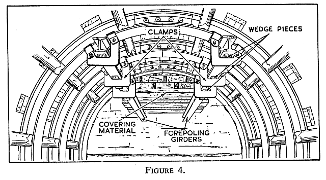
The forepoling girders may be designed in such a way that they carry the supports for the face of the ripping. At some mines canopies have been made which are designed to give cover and protection to the workmen throughout the operation of advancing a roadway.
GATE SIDE PACKS
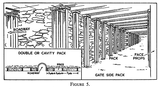
Stone removed as the roadway is being made, or stone brought specially into the district, is packed on each side of the roadway (gate) to support the roof. These packs which consist of tightly rammed material enclosed in walls of larger stones wedged firmly between the roof and floor are usually of greater width than the packs described in Training Manual No. 2.
In some places it has been found that better roof conditions have been maintained if the packs on each side of the roadway have been built in two sections as shown in Figure 5 (inset). This is called 'double' or 'cavity' packing.
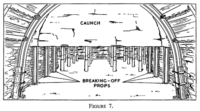
BREAKING OFF PROPS
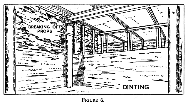
These are props which are set around the edge of the area of roof or floor from which the rock is to be blasted in order to obtain the height required in the roadway. Where rocks have to be removed from the floor (dinting) the breaking off props are set as shown in Figure 6. Figure 7 shows how the props should be set when the rocks from the roof have to be removed.
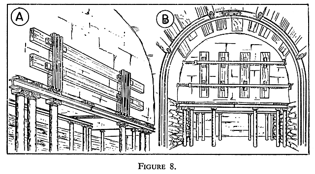
RIPPING FACE SUPPORTS
These supports, as shown in Figure 8, provide support to the face of the ripping. There are various types; one, as shown in Figure 8A, consists of bent corrugated steel bars behind which wooden planks are wedged. Another type, shown in Figure 8B, consists of adjustable stretchers which are fitted across the roadway.
STRUTS
Should roof movements within the roadway occur so that a girder becomes unevenly loaded, it may buckle. Struts, pieces of wood or steel, are inserted between each pair of girders to help it resist buckling, and thus ensure rigid support. Struts may be used to ensure that the roadway girders are set at the required distances apart.
There are different types of struts, some of which are shown in Figure 9.
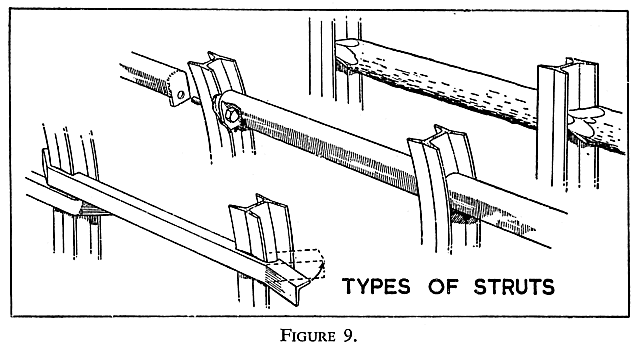
With arched girders, struts which bolt to the girder have the added advantage that they can be used to hold the halves in position until the fishplates are attached.
Sequence of Operations in the Setting of Supports in Roadways
The operations which together make up the work of advancing a roadway are usually carried out in a definite sequence. It is usual, first of all, to set the breaking off props and to drill the shot holes in their appropriate places. The supports within the breaking off props are then withdrawn, the shot holes charged, and blasting operations carried out. Where the rocks above the seam are removed, the roof, newly exposed by the blasting, is made secure from the forepoling girders which are advanced immediately. The sides of the roadway and the face of the ripping are then trimmed of loose pieces of rock, the face of the ripping being supported as soon as possible.
The broken rock debris is then built into packs on each side of the roadway.
As soon as sufficient rock has been removed to allow permanent supports to be set, straight, cambered or arched girders are erected to secure the roof. The distance between each of these supports is decided by the manager and can be found in the Colliery Support Rules which are posted at the surface of the mine.


 |
 |
 |
||

Back |

Home |
Copyright © 1999-2012 by The Durham Mining Museum and its contributors
Page last updated: 01 Jan 2008 |

Search |

|