


Mail: Webmaster

|

|

|

|
|
 |
 |
|||
Chapter IV
Accessories
Wet Cutting
 Where coal cutting produces much fine dust, arrangements are made for water sprays or jets to be fitted to the machine to damp the cuttings and to allay the dust.
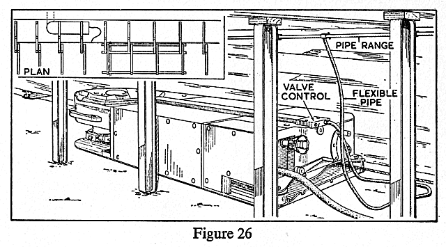
A typical layout for a longwall face is shown in Figure 26, where a range of pipes, about 1" in diameter, is placed along the face. At intervals of about 30 yards 'T' pieces are inserted into the range, a length of ½" diameter hose being used to connect the machine to these points. The hose is connected at the haulage end of the machine to a ½" diameter pipe which runs along the top of the machine, or in a specially made groove in the casing from the haulage end to the gearhead. This pipe may be connected to nozzles fitted at several points along the jib or to one or two nozzles fitted to the gearhead (Figure 27). The diameter of the nozzles may vary from ¼" to 3/8". In some cases the nozzles may be elliptical in shape. The water from these nozzles is directed on to the chain where puddles are formed, and the chain as it passes round carries sludge into the cut, where it is mixed with the dust and smalls. In this manner the dust clouds are damped down.
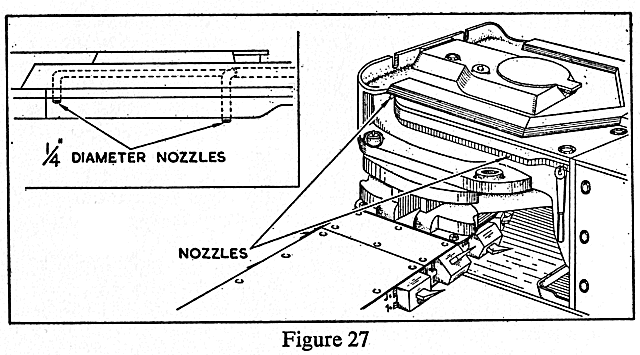
Where overcutting machines are used, special sprays are attached to the machine to reduce the amount of airborne dust.
Flexible or Trailing Cables
The purpose of a trailing cable is to carry power from the gate end switch to the machine. A cable for such purposes is made up of four or five cores or conductors, each made up of a number of strands of fine tinned copper wire which are encased within a rubber covering which acts as an insulator. The cores themselves are wound spirally together and enclosed in a tough sheath (Figure 28). In the sheath there may be embedded a braid of fine copper wires. This braid in other cases may be wrapped round the rubber surrounding each individual core. This copper 'screen', as it is called, acts as a screen between the live conductors and the outside of the cable, giving extra protection for the user should the cable become damaged.
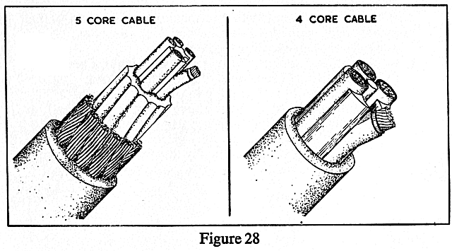
Where a four-core cable is used it will be used with the 'Direct On' or 'Local Control' system. In this, the working voltage is on the cable from the time the supply is switched on at the gate end switch box until it is switched off again. The power supply to the motor itself is controlled locally at the machine switch as was mentioned on page 6.
A five-core cable is used when the 'Remote Control' system is employed, the extra core being used to complete a pilot or lowvoltage circuit. The machine switch operates the 'pilot circuit' which in turn causes the main switch in the gate end box to operate. This system is the one most favoured since it ensures, among other things, that the working voltage is applied to the cable only when the motor is running.
The contactor pin of the pilot circuit in the plug socket is shorter than the main contactor pins. The plugs have, therefore, to be properly inserted into the sockets before the power can be switched on.
CARE OF CABLES
| 1. |
A cable should be suspended from the roof supports to prevent its being buried by falls of stone or coal.
|
|
| 2. |
Where arrangements can be made, always have the cable in front of the machine. Where this is not possible, some form of guide should be placed on the machine, to carry the cable over the top of the machine, ensuring thereby that the cable will not fall off and be caught by the picks.
|
|
| 3. |
Before the plug is placed into the socket, ensure that both are clean and dry.
|
|
| 4. |
The plug should be locked firmly in the socket to ensure continuity of circuit. The plug should never be hammered into a socket.
|
|
| 5. |
When the cable has to be bent back over the machine after it has been plugged into the socket, the bend should make a wide arc so as to reduce the risk of breaking the conductors.
|
|
| 6. |
Trailing cables are not made to withstand strong pulls. If the cable connected to the machine appears to be fast in any way, stop the machine and free the cable. Never allow the machine to drag the cable.
|
|
| 7. |
Cables should be carefully protected from damage by flying fragments of rock or coal during shot-firing.
|
|
| 8. |
Cables should not be left lying in pools of water.
|
|
| 9. |
Cables should be suspended above all machinery and not left to come into contact with any moving parts.
|
|
| 10. |
Cables should be coiled carefully after use (Figure 21).
|
|
| 11. |
Cables should be systematically overhauled and should receive periodic overhaul in a central cable repair depot.
|
Air Hose
A trailing hose suitable for use with coal cutting machines is made of braids of woven fabric separated by layers of rubber.
The fabric gives strength to the hose. The hose is protected against abrasion by a cover of tough rubber.
Metal air pipes are taken as near as possible to the face in order to reduce the length of trailing hose that is needed. The diameter of the hose in use should not be less than 2" to ensure that the pressure drop in the hose is kept to a reasonable figure.
HOSE COUPLING
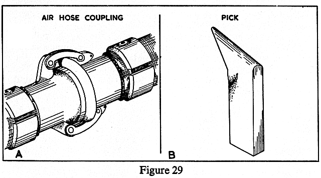
The joint between two hoses should be airtight. One type of coupling is shown in Figure 29A.
Cutter Picks
The efficiency of every coal cutting machine is dependent upon the cutter picks used. They are shaped pieces of steel which have been given special heat treatment to make them resistant to abrasion and continued 'shock'.
A tougher and harder pick than an ordinary standard pick is made by using tungsten steel. The 'tipping' of a pick with a hard metal such as tungsten carbide increases the number of yards it will cut without requiring to be changed.
The points of the picks should be set to cut full on the material holed, and the point should lead the body by about ½" (Figure 29B).
Chain
The chain is made up of a series of pick boxes coupled together by various means depending upon the type of chain in use.
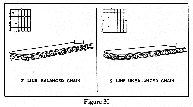
The picks are set at different angles to the chain, and a chain is 'balanced' when the number of picks above the centre pick line is the same as the number of picks below. Where there are more bottom picks than top picks the chain is then said to be 'unbalanced' (Figure 30).
When picks are placed in the boxes, a gauge should be used to check that all the picks in the same line project by the same amount (Figure 14). If some picks project more than others, or if any box is left without a pick, there will be unequal sharing of the work by the picks in the chain.
If the top picks project more than the bottom picks there is a tendency for the jib to rise during cutting, and if the bottom picks project too much the jib will tend to dig into the floor.
The setting of the picks may vary with the material being cut, the proper setting being obtained only by experience.
Protective Devices attached to Electrically Powered Machines
PROTECTION AGAINST SELF-STARTING
With a Remote Control System, if there is a power failure whilst the machine is working, the operator may forget to return the control switch to the 'off' position. When the power is restored the machine will then start up. To prevent this, the electrical circuit is designed in such a way that the control switch on the machine must be switched 'off' and then switched 'on' before the machine will restart.
PROTECTION AGAINST RAPID SWITCHING
If the operator were repeatedly to switch the supply 'on' and 'off' very quickly this would cause burning of the contacts in the gate end switch box. This might result in serious damage to the switchgear, or the district circuit breaker might be tripped. The gate end switch may therefore be fitted with a device to prevent rapid switching.
EARTH CONTINUITY
This ensures that the machine is properly earthed to the gate end box before the power supply can be completed.
A low-voltage supply is carried by the pilot core returning to the gate end box through the frame of the machine, the earth core and the frame of the gate end box. If there is a break in this circuit it is not possible to complete the power supply to the machine.
The circuit is made intrinsically safe by connecting a suitable device in the circuit to absorb the energy which may otherwise produce incendive sparking. (See N.C.B. publication, The Maintenance of intrinsically Safe Apparatus.)
PILOT EARTH CORE PROTECTION
The electrical gear is so designed that should anything cause contact to be made between the pilot core and the earth screen or earth core the switch in the gate end box is tripped. This is intended to prevent the plug which the operator may be carrying becoming 'alive' if a cable with a fault of the kind described is plugged into the gate end box and the switch is placed in the 'on' position.
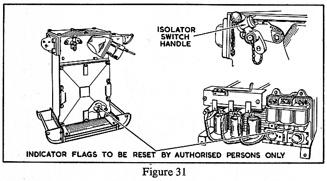
In some types of switchgear, when the switch is tripped a white flag will be seen through the small glass window in the switch box casing. A special key is necessary to reset the flag. This must be done only by an electrician.
EARTH LEAKAGE PROTECTION
Should a cable become damaged in such a way that one of the power cores makes contact with the earth screen or with the framework of the switch box or machine, this protection will instantly trip the main switch and, in some types of switchgear, drop an indicator flag into view at the small glass window. As in the case of the pilot earth core protection a special key is used to reset the flags and this must be done only by an electrician.
OVERLOAD PROTECTION
A motor which is overloaded becomes overheated. The overload device prevents this by causing the electricity to be switched off at the gate end box.
UNDER-VOLTAGE PROTECTION
Provision is made for isolating the power supply in the event of an excessive voltage drop, usually 60% or 65% of the rated value.


 |
 |
 |
||

Back |

Home |
Copyright © 1999-2012 by The Durham Mining Museum and its contributors
Page last updated: 01 Jan 2008 |

Search |

|