


Mail: Webmaster

|

|

|

|
|
 |
 |
|||
Chapter II
Operating the Machine
 It is advisable to examine and run a machine for a time before it is sent underground, after delivery from the makers, or after it has been overhauled.
A cutting machine is usually transported on a specially constructed trolley to the district in which it is to work. It usually travels as one complete unit, except for the jib and chain which are attached when the machine has been unloaded. The jib is bolted into position the chain placed round the sprocket and the ends riveted together before the machine is drawn into the face. It is again advisable to examine and run the machine before the operator takes over.
The Operator's Preliminary Examination
Before starting the machine the operator should make a preliminary examination as follows :—
1. Check the trailing cables or air hoses for damage.
With air machines, blow air through the hose to remove any dust or water before coupling up to the machine.
With electric machines, ensure that:
| (a) |
the cable has not been damaged in any way;
|
|
| (b) |
the isolator switch on the gate end box is in the 'OFF' position;
|
|
| (c) |
all plugs and sockets on the cable, the machine, the gate end switch box and any cable couplers are clean and dry;
|
|
| (d) |
there are no kinks in the cable when it is laid out on the face;
|
|
| (e) |
the switch on the machine is in the 'OFF' position
|
|
| (f) |
the plugs fit the sockets and lock in position.
|
2. Couple the trailing cables or air hoses.
| Note: |
(a) The cable should be coupled to the machine before it is coupled to the gate end switch box.
|
|
|
(b) In Remote or Local Control circuits the Pilot core pins in the socket are made shorter than the power circuit pins as a safety precaution. The plug must therefore fit well into the socket before the power can be switched on.
|
||
|
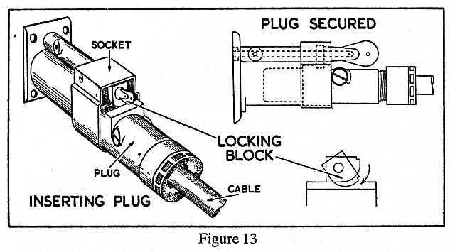
(c) When placing the plug in the socket, see that the locking block is in the correct position. The curved portion of the block should be at the right-hand bottom corner (Figure 13 inset). This allows the block to revolve into a groove on the plug, making the locking device operative.
|
3. Turn on the compressed air in the gate or, with electric machines, place the isolator switch at the gate end switch box in the 'ON' position.
4. See that the chain is free from obstruction.
5. Operate the switch handle at the machine and switch on the power momentarily to make sure that power is being supplied to the machine.
With electric machines engage the chain by means of handle 'F' just before the motor stops. This will show the direction of movement of the chain and the direction in which handle 'A' must be turned for forward or reverse chain movement. Disengage the chain. At the same time check that the rope is wound correctly on the haulage drum.
6. Oil the machine. (See notes on Daily Lubrication, page 23.)
7. Examine the chain for correct tension. Where necessary tighten the chain as follows :—
| (a) |
Remove the jib cover plate;
|
|
| (b) |
Place the end of a tommy bar into the holes of the adjusting screw;
|
|
| (c) |
Turn the screw until the chain is tightened sufficiently to allow only a small amount of play of the chain in the race;
|
|
| (d) |
Replace the cover plate and secure.
|
8. Place a sharp pick in every box of the chain so that the point of each pick faces the direction in which the chain is to travel when cutting.
| Note: |
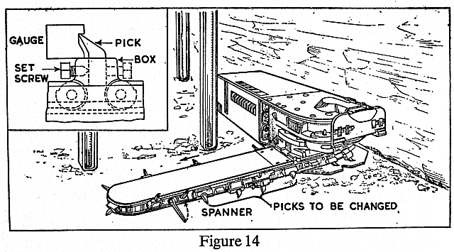
(a) Where there are two tapped holes to a box the screw in the leading hole in the box should be used to secure the pick (Figure 14).
|
|
|
(b) A special gauge should be used to check that the pick projects the right distance from the box. Tighten the set screw.
|
||
|
(c) It should not be necessary to use a pipe or wrench with the spanner to free the set screws. A note should be made in the daily report of any screws which cannot readily be turned by the spanner.
|
9. Fix a guard in position as soon as it is possible to do so.
10. Run out the haulage rope by hand or by using power.
In the case of electrically operated machines :—
Place handle 'C' in the high speed position.
Switch on the motor in the direction which runs the rope off the drum.
Where the machine is operated by compressed air :—
Engage handle 'B' to reverse the direction of the haulage drum.
Switch on the power and draw off the rope.
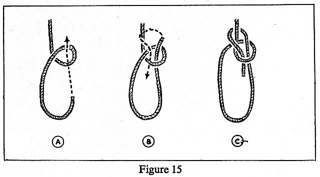
11. Examine the rope, especially at the loop end. If this is damaged, cut off the loop, using a hammer and chisel, and make a fresh loop as follows :—
| (a) |
Thread the end of the rope to form a knot as shown in Fig. 15.
|
|
| (b) |
Attach the loop to the anchor prop, and tighten the knot by drawing the rope on to the drum.
|
If, however, the rope is damaged or worn so as not to be fit for further use, fit a new one.
Jibbing In
1. Set two stay props at the side of the machine away from the face to keep the gearhead close to the face whilst the operation of jibbing in is carried out. Place a short sprag between the face and the haulage end to keep the control handles free and also to enable the rope to be removed after jibbing in.
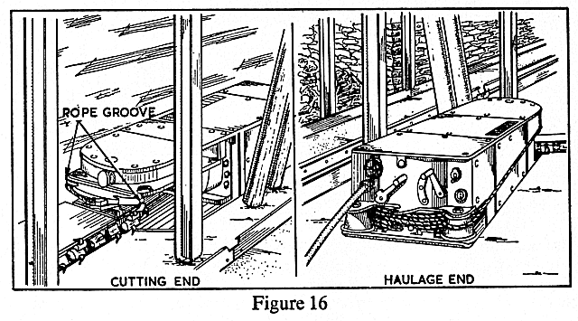
2. Pass the haulage rope round the machine on the face side as shown in Figure 16.
Attach the loop of the rope to the bracket on the turntable or, if a slewing chain is used, attach the loop of the rope to one hook of the slewing chain, and the hook on the other end of the chain to the turntable.
3. See that the jib locking pin is disengaged or removed.
4. Make sure all persons are well clear of the jib.
5. Place the haulage clutch handle 'C' in the cutting position; ensure that, in the case of a machine operated by compressed air, handle 'B' is set to draw the rope on to the drum. Switch on the power and engage the friction clutch handle 'E'.
6. Operating the handle 'D', tighten the rope, ensuring that the rope-chain rests in the groove of the gearhead.
| Note: |
The groove ensures that the rope will not fall and foul the picks.
|
7. Draw the jib round until the picks are almost touching the coal face.
8. Switch off the power, and, just as the motor is stopping, engage the chain clutch 'F'.
9. See that the chain is free to rotate.
10. Switch on the power.
11. Jib in slowly and stop the feed, using handle 'D', as soon as the machine shows signs of labouring.
12. When the jib has cut well into the coal, shovel away the gummings to prevent the chain becoming choked up. Stop the machine whilst this work is carried out.
13. As the jib reaches the cutting position, drop the jib pin into its hole and lock the jib in position.
| Note: |
Care must be taken at this stage not to put any undue strain on the haulage rope; therefore stop the feed by turning off handle 'D'.
|
14. Allow the cutting chain to continue to spin round a few times so that it keeps itself free; release clutch 'E' then switch off the power.
15. Release the haulage rope by placing the haulage clutch handle 'C' in the neutral position. Remove the slewing chain.
16. Clean the gummings from the cut, and insert a nog near to the jib to prevent the coal lowering and fastening the jib.
17. Attach either a guard or a gummer together with the necessary guards.
GUARD
Where no gummer is used, a guard is attached to the gearhead to prevent personal injury from the moving chain. It is attached to the gearhead as shown in Figure 12.
GUMMER
| (a) |
Clean up the cuttings round the gearhead.
|
|
| (b) |
It may be necessary on some types of machines, when the direction of the cut is opposite to that of the cut previously made, to reverse the drive of the gummer. This is done by turning the reversing spindle shown in Figure 10 in an anticlockwise direction, at the same time slowly rotating the worm of the gummer. This allows the reversing gear to be engaged.
|
|
| (c) |
Take off the cover protecting the dog clutch. Attach the cover to the machine or put it in a place of safety. Remove any dirt from the face of the dog clutch.
|
|
| (d) |
Attach the gummer and deflection shield to the gearhead.
|
| Note: |
Care must be taken about the position of the gummer in relation to the cutting chain. If it is too near, the picks may cause damage; if too far away, the function of the gummer is impaired.
|
Cutting
1. Prepare the cutting track when the machine is running on the floor. Clear away loose coal, debris or other material from the path of the machine.
| Note: |
Where it is necessary during the preceding shifts to set supports directly in the cutting track to secure the roof, set fresh supports so that they will secure the roof but be out of the cutting track. Any supports in the path of the machine may then be removed as the machine approaches.
|
2. Draw off the haulage rope as previously indicated on page 15 and pass the rope round the face side pulley as shown in Figure 17 (inset).
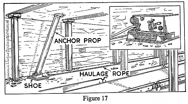
3. Set up an anchor prop at a distance from the machine almost equal to the length of the haulage rope, leaving one or two laps of the rope on the drum. Make a notch hole in the roof with a pick, and insert the top of the anchor prop into the hole. Place the loop of the haulage rope in the hook attached to the anchor prop (Figure 17).
| Note: |
(a) Different types of anchor props are used at different collieries.
|
|
|
(b) In seams with soft floors, it may be necessary to place the foot of the anchor prop in a specially made shoe or shackle to prevent the foot of the prop penetrating the floor and thus allowing the prop to be pulled out.
|
4. Take up any slack rope and gradually tighten the rope, using the slow speed to test the anchor prop to see that it is secure.
| Note: |
Stand clear of the anchor prop whilst carrying out the operation.
|
5. Switch off the power, and as the sound of the motor dies away, engage the chain by means of handle 'F'.
6. Switch on the power and allow the chain to pick up speed.
7. Engage the friction clutch handle 'E'.
| Note: |
The friction clutch handle is always the last to be engaged when the machine is to be moved and the first to be disengaged when the machine is to be stopped.
|
8. By operating handle 'D' control the rate of advance of the machine.
9. An assistant to the machineman should remove debris from the cut, using the long handled shovel. Drive cutting nogs or sprags into the cut every 6' or less if required. A nog should be placed directly alongside the jib when the end of the rope has been reached (Figure 18).
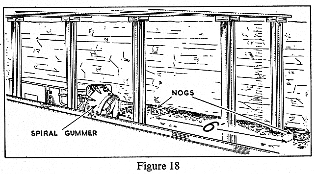
10. On reaching the anchor prop disengage the friction clutch handle 'E' and then clutch handle 'C' and turn off the power.
11. Remove and reset the anchor prop farther along the face, draw out the haulage rope and attach it to the prop.
12. Repeat the sequence of operations until the end of the face is reached.
Drawing the Machine from the Face at the End of the Shift
There are many ways in which machines may be drawn off the face out of the way of filling operations at the end of the cutting shift. One method is described below :—
1. Remove the gummer or the guard when the machine has reached the end of the cut.
2. Remove the anchor prop and draw off a length of haulage rope. Reset the anchor prop in the required position for the next move and attach the loop of the haulage rope.
3. Place the stay or sprag near the centre of the machine toward the haulage end. This will act as a pivot (Figure 19).
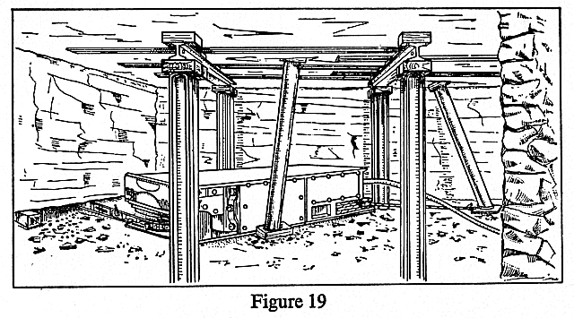
4. Switch on the power and draw the machine into the required position.
| Note: |
The cutting chain is still engaged.
|
5. Reset anchor prop in new position and repeat.
6. Disengage the jib pin when the machine is almost at right angles to the face.
7. Reset the anchor prop. By controlling handle 'D' draw the machine towards the anchor prop until the jib is drawn out of the cut (Figure 20). Disengage the chain clutch so that the cutting chain no longer revolves.
| Note: |
The machine should always be left in a well-ventilated position and under secure roof.
|
|
|
The face bars set at the ends of the face must be supported by long carrying bars, which allow some of the props to be removed from the path of the machine without leaving the roof unsupported. These carrying bars must also be used in places where machines have to be turned round.
|
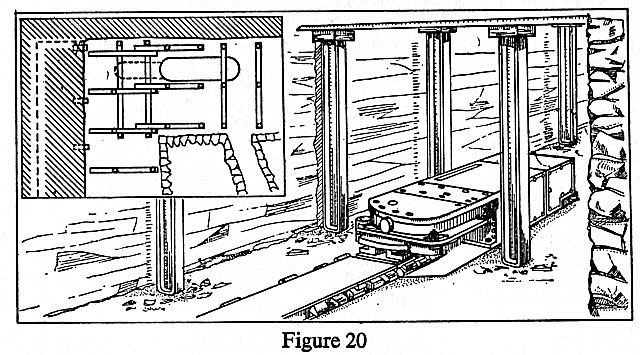
8. Reset any supports that have been removed. This will help to protect the machine from any roof stones that may be likely to fall.
9. Remove all the picks from the chain. Examine the chain for wear and any damaged links. Reference should be made in the daily report to any wear or damage so that the parts may be repaired or renewed before the next cutting shift.
| Note: |
If necessary, lubricate the chain.
|
10. Switch off the poweratthe machine and atthe gate end switch.
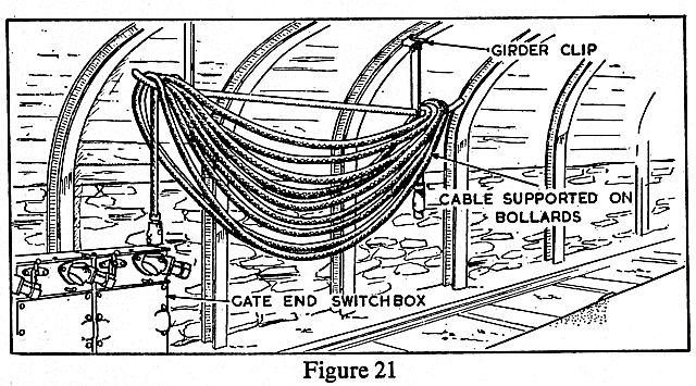
11. Remove the cable or hose. A trailing cable should be disconnected from the gate end switch box first. Hang the cables on special carrying devices or stow them in a safe place in the gateway in the form of figure' 8 '(Figure 21).
| Note: |
A cable should be properly stowed so that the wires inside do not come under any stress which may eventually cause them to break. Suspending cables from the roof on carrying devices will ensure that they are not left lying in pools of water which may have harmful effects on them.
|
Drawing the Machine into Position at the Commencement of the Shift
1. Attach the trailing cable or air hose as before. Insert sharp picks into the boxes, making sure that the picks are inserted in the correct way.
2. Lock the jib in the extended position.
| Note: |
See that the chain is free to rotate. Make sure the floor is even so that the jib will enter the coal parallel with the floor.
|
3. Set the anchor prop as shown in Figure 22 and attach the haulage rope.
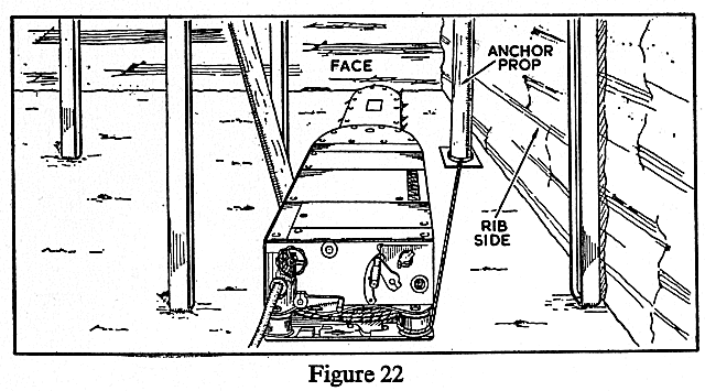
4. Switch on the power and move the machine until the tip of the jib is almost touching the coal (Figure 22).
5. Switch off the power, and just before the motor stops, engage the chain clutch 'F'.
6. Switch on the power and engage the friction clutch 'E'. By operating the variable cutting speed handle 'D', drive the jib into the coal.
7. Switch off the power and take the chain out of gear. Release the haulage rope and disengage the jib pin.
8. Reset the anchor prop to draw the haulage end of the machine round to the face.
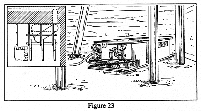
9. Attach the haulage rope to the anchor prop (Figure 23). Draw the machine round until the jib pin can be engaged. Engage the jib pin. Switch off the power.
10. Release the haulage rope and reset the anchor prop in the cutting position. Proceed as before.
Flitting
A machine can be 'flitted', i.e. moved from one position to another when not cutting, with the jib either trailing or in front. The procedure when the jib is trailing is similar to that when cutting except that the haulage clutch handle 'C' is in the high speed position. To keep the machine straight the rope is threaded round a pulley which is attached to the centre of the haulage end.
When flitting with the jib in front the haulage rope is passed round the pulley at the haulage end and round a bracket and pulley attachment fitted to the jib (Figure 24). The chain clutch handle 'F' is disengaged and the haulage clutch handle 'C' placed in the high speed position.
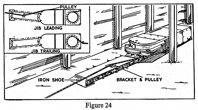
The machine can be kept in its path when it is being moved by setting sprags to the side of the machine. In seams where the floor is soft a special iron shoe (Figure 24) may be fitted to the tip of the jib to prevent its digging into the floor.
Care should be taken when moving a machine at flitting speed to prevent the cable being trapped.


 |
 |
 |
||

Back |

Home |
Copyright © 1999-2012 by The Durham Mining Museum and its contributors
Page last updated: 01 Jan 2008 |

Search |

|