


Mail: Webmaster

|

|

|

|
|
 |
 |
|||
Chapter I
Introduction and General Description
Introduction
 Coal cutting machines are often used underground to assist in breaking down the coal so that it can be loaded out. A coal cutter cuts into a portion of the seam, making a slot along the coal face, after which the remaining part of the coal is cut down by the use of hand or pneumatic picks or is broken down by explosives.
The slot made by the cutting machine is known as the 'cut' or 'kerf'. Normally the cut is 5" or 6" high and penetrates the seam to a depth of 4' 6" or 6', although cuts are sometimes made as shallow as 2' and as deep as 7'.
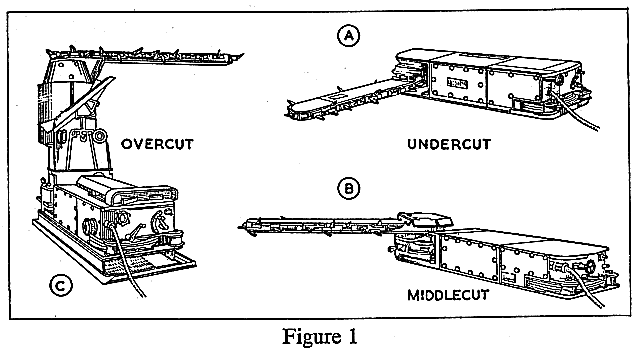
If the cut is made at floor level, the seam is said to be 'undercut'. If halfway up the seam it is called a 'middlecut', and if at the top of the seam, near the roof, an 'overcut'. Machines designed for these three cutting positions are shown in Figure 1.
General Description
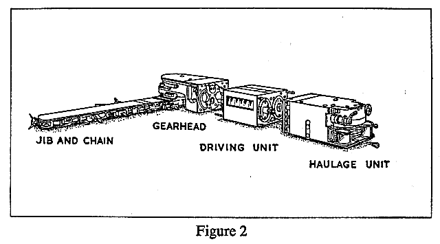
A coal cutting machine is made up of three main parts which are bolted together as shown in Figure 1, but which can be separated as shown in Figure 2. These parts are:
| 1. |
The Driving Unit containing the motor.
|
2. |
The Haulage Unit which carries the operator's controls.
|
3. |
The Gearhead, to which are attached the jib and cutter chain, and (if one is in use) the gummer.
|
1. The Driving Unit
This is the central section of the machine. It consists of a casing enclosing the motor which drives, through a series of gears, the haulage and cutting units. The driving unit may contain either an electric motor or a compressed air turbine. The power of the driving unit may be either 40, 50 or 60 h.p., according to the type of machine. The supply for electrically driven coal cutting machines is normally alternating current and is supplied to the machine at a voltage of 440, 500 or 600 volts. Compressed air is usually supplied at a pressure of about 60 lb. per square inch.
Electrically driven machines are fed by a flexible cable, called a trailing cable, which is coupled at one end to the main supply in the gate end box and at the other to the machine. The point where the trailing cable is connected to the main supply is a gate end switch by which the current can be switched on to or shut off from the trailing cable. At the machine itself there is a controller switch which is used by the operator when working the machine. The power may be cut off either in the switch compartment of the driving unit, or in the gate end switch box. In the former 'Direct On' type, the controller switch handle on the machine operates directly the main switch in the machine. In the latter 'Remote Control' type the controller switch handle operates the main contactor switch in the gate end box through a pilot circuit.
The electric motor consists of two sections, a stator and a rotor. The stator is the fixed part of the motor consisting of a series of wires arranged in coils set around the rotor. The rotor is an iron core cylinder, at each end of which project the driving shafts. When the current is switched on, a magnetising field is produced in the stator windings and magnetism is induced in the iron core; this causes the rotor to turn.
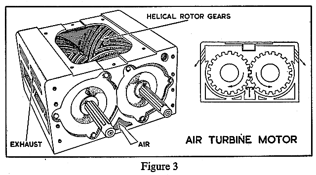
With compressed air driven machines the air is fed along the gate in steel pipes through a main control valve to 2" diameter rubber hose, and so to the machine where the air is controlled by another valve operated by a handle attached to the haulage end of the machine. The compressed air turbine is shown in Figure 3. It consists of two cylinders called rotors, on each of which are a number of teeth which radiate diagonally from the centre point of the rotor to the outside edge. These are called double helical gears and those of each rotor are designed to mesh together. The air is conducted through a pipe underneath the turbine and is fed to the helical gears at the point where they meet at the centre of the rotors. The compressed air with its high pressure forces the teeth of both rotors apart, causing the rotors to revolve. This movement continues as each succeeding pair of teeth come under the influence of the compressed air.
2. The Haulage Unit
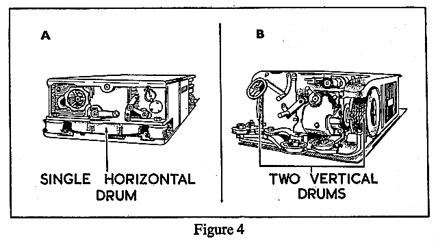
A flexible steel rope either ½" or 5/8" in diameter and about 30 yards long is used to pull the machine along the face. At one end of the rope there is an eye or loop for attaching to an anchor prop. The other end of the rope is wound round and clamped to a drum attached to the haulage unit. As shown in Figure 4A there may be only one drum placed horizontally almost at floor level at the centre of the haulage unit, or as shown in Figure 4B there may be two vertical drums, one at each side of the unit.
[Where a coal cutting machine is run on the top of an armoured conveyor a different haulage arrangement is used. The rope is lapped round the haulage drum, one end of the rope being anchored at the end of the face and the other end anchored at the other end of the face.]
The gearing through which the motor drives the haulage drum is contained in the unit above the horizontal drum, or between the two vertical drums. The haulage unit also carries the controls which the operator uses to work the machine. These are shown in Figure 5 lettered A to E as follows :—
| (A) |
The starting switch handle or air control valve. (On electric machines this switch or controller is also used to reverse the direction of the motor.)
|
|
| (B) |
The handle for reversing the haulage drum on compressed air machines.
|
|
| (C) |
The clutch handle (sometimes called the gear lever) for engaging high and low speed gears to the haulage drum.
|
|
| (D) |
The speed control handle for varying the speed when the haulage drum is in low gear.
|
|
| (E) |
The quick release lever for the rope or friction clutch.
|
The handle for putting the cutting chain into gear is in some machines placed with the other controls on the haulage unit. In other machines it is situated at the side of the gearhead as shown at F in Figure 5. With compressed air machines in which the motor is not reversible the direction of the cutter chain is also reversed by this handle.
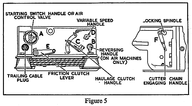
The clutch handle (C) is placed in the high speed position when moving the machine quickly during flitting and in low speed when cutting. Fine control of cutting speed is obtained by using the speed control handle (D).
With some machines a strong chain is used in place of the flexible steel rope.
3. The Gearhead
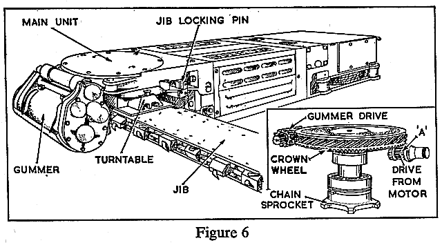
The gearhead contains the mechanism by which the cutting chain is driven round. A bevelled pinion A (Figure 6) from the shaft of the motor drives the chain sprocket through a large diameter horizontal bevelled gear, called a 'crown wheel', and a sprocket shaft.
On some types of coal cutting machines, emergency stop switches are fitted to the gearhead.
Supported in the gearhead below the crown wheel is a ring or turntable which carries the jib. This is free to turn, thus enabling the jib to be slewed from one position to another as shown in Figure 7.
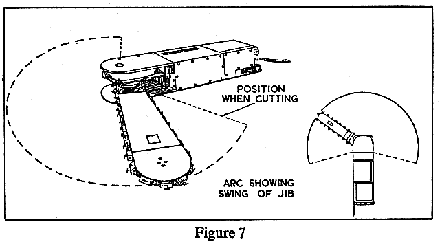
Fastened to the turntable is a bracket into which the support bar of the jib is fitted.
The turntable may be locked by a jib locking pin, which in some machines is a bolt fitted into the framework of the gearhead as in Figure 6.
The gummer is also driven from the crown wheel, as is shown in the inset of Figure 6.
The jib shown in Figure 8 is constructed of steel plates riveted together to provide the framework round which the chain will rotate. This framework is carried by a support bar or jib post which is slotted into the bracket of the turntable on the gearhead and bolted to it. The other end of the support bar is connected to the framework of the jib by means of an adjusting screw shown in Figure 8. This screw enables the jib to be moved along the bar so that the tension in the chain may be varied.
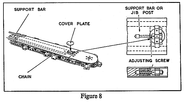
Round the outside end of the jib is a channel or race which provides the track for the chain. It is made up of strips of special wear-resisting steel.
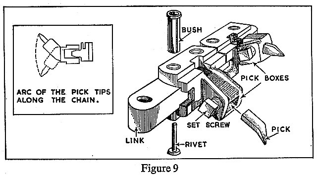
The cutter chain shown in Figure 9 is one of the various types of chains which are used. They consist of a series of pick boxes joined together in various ways. One end of the chain is threaded round the race on the jib, passed round the driving sprocket, and the two ends of the chain are then riveted together. The cutter picks are held in the pick boxes by a set screw. The pick boxes along the chain are set at different angles so that the picks are fanned out to cut on a series of lines. Some of the pick boxes are arranged to take two picks, one pointing upwards and the other downwards. These are called double boxes.
A loose cutter pick is shown in Figure 9. After forging to the best shape to achieve good cutting results the steel is hardened to resist wear. For very hard cutting the pick may also be tipped with a special hard alloy.
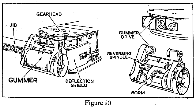
As the machine cuts, the chain brings out from the cut the pieces of coal which it has chipped off. These are called gummings. Unless these are cleared as they are brought out, either by hand shovelling or by some mechanical device, they get carried back into the cut and may choke the chain and so stall the machine. To save hand shovelling, mechanical gummers are fitted to undercutting machines. As mentioned previously, the gummer is driven from the crown wheel. There are three main types of gummer:
| (a) |
The spiral worm type as shown in Figure 10. The main component of this is a large diameter worm into which the gummings are pressed as they are brought out by the chain. The worm then screws them out away from the machine. Spiral gummers are made either to deliver to the side, as shown in Figure 10, or behind the machine.
|
| (b) |
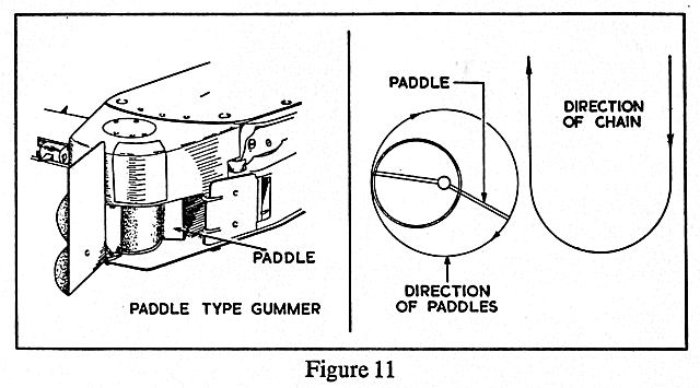
The paddle type is shown in Figure 11. In this type a rotating paddle scrapes out the gummings away from the chain and discharges them behind or to the side of the machine.
|
| (c) |
The Stower type, which picks up the gummings as they are discharged from the cutting chain and ejects them into the goaf or waste.
|
In some mines a gummer bar is attached to the gearhead of a machine when cutting. The bar projects under the cut close behind the jib and is designed to increase the amount of gummings removed from the cut.
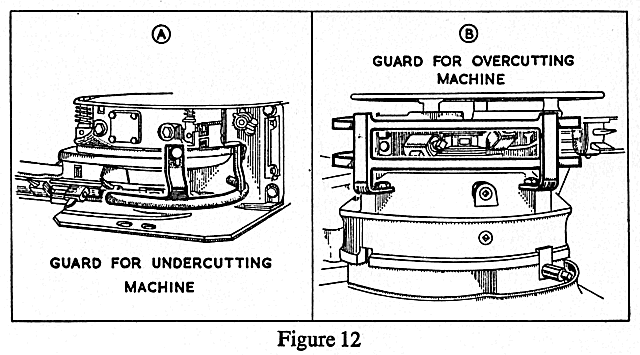
Safety guards are attached to the gearhead. These are to prevent injury to anyone working close to the cutter picks. The guard shown in Figure 12A is designed for use with an undercutting machine when no gummer is used, and that shown in Figure 12B for use with an overcutting machine.


 |
 |
 |
||

Back |

Home |
Copyright © 1999-2012 by The Durham Mining Museum and its contributors
Page last updated: 01 Jan 2008 |

Search |

|