


Mail: Webmaster

|

|

|

|
|
 |
 |
|||
Chapter II
Installation

Preparation of the Roadway
1. It is most important that the conveyor should be installed in a straight line. To enable this to be done, a line should be provided to which the conveyor must be set. It may be a whitewash line on the roof, or, if practicable, a wire stretched along the roadway near the roof. It is usual for the surveying staff to mark the position of the line.
The conveyor is aligned by suspending a plumb bob from the line (Figure 11).
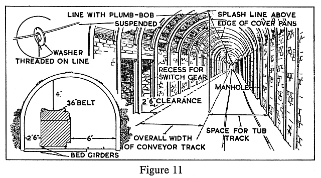
Where the wire method is used, a number of washers should be threaded on to the wire to which the plumb bob can be tied for sliding along.
The line is sometimes placed over where the middle of the conveyor is to be. Alignment is easier, however, if the line is placed over the edge of the conveyor nearer to the centre of the roadway.
2. Make sure by measurements from the plumb bob suspended from the line that there is enough room along the whole length of the conveyor, when it is in position, for a tub track along one side. There should also be enough room on the other side to enable the largest lump that might fall off the conveyor to fall clear, so that it does not continue to scrape the belt. The amount of clearance on this side should also be enough to permit easy inspection and cleaning.
3. Clear the floor, and level it across the road. Smooth out any sharp changes in gradient (dip) along the road (Figure 12).
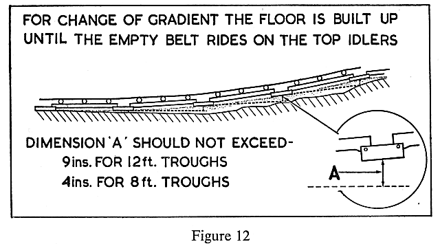
A sharp curve upwards may cause the top belt when empty to ride away from the idlers and then as the load comes on the belt is forced down on to the idlers. Such an occurrence increases the tension in the belt and if it is not centrally loaded the belt may be forced to ride away from the structure and cause spillage.
A sharp curve downwards will cause extra pressure on the idlers.
4. Lay a tub track so that it will allow the tubs to pass without catching the conveyor. If there is one already present make sure that the same clearance exists.
5. Take each part, e.g., return drum, intermediate structure, driving gear, delivery end, and belting to its right place along the roadway.
Preparing the Position for the Drive
1. Select the position.
(a) The drive must be carefully positioned to enable the coal to be delivered correctly into the tub or trunk belt, whichever is used. If the conveyor is fitted with a jib head extension, the drive will be set back in the roadway a distance equal to the length of the jib, which will depend upon the particular conveyor.
(b) If tubs have to pass under the jib head the roadway must be of sufficient height to allow for this and for the passage of large pieces of coal on the belt.
(c) The width of the roadway should be such as to allow for a tub track on one side and for inspection of the machinery on the other side, as shown in Figure 11.
It may be necessary to widen the roadway at this point to make room for the motor, and to grade the roadway so that the tubs will gravitate from the loading point.
2. Construct a recess free from inflammable material for the switchgear and fire appliances (Figure 11). This recess should be well clear of the conveyor so that this equipment is readily accessible in case of need.
3. Construct any brick or concrete work that may be necessary for the support of the roadway at this point or for carrying the bed girders.
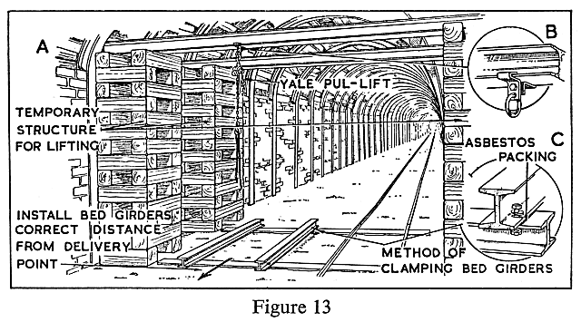
4. If necessary, erect steel girders, to which lifting tackle can be attached, across the roadway above the site for the drive. Two or three girders at distances apart of 2 or 3 ft. may be necessary according to the size of the machine. They may be set as permanent fixtures in the drive position or they may be set temporarily on chocks as shown in Figure 13A, to be removed when the drive has been assembled.
Installing the Drive
1. Place the bed girders in the positions selected and level them accurately across the roadway, using a spirit level.
| Note: |
As a precaution against fire, avoid the use of wood anywhere about the drive-head.
|
2. Using suitable lifting tackle and lifting jacks where necessary, build up the drive in its position and line it carefully with the line on the roof.
| Note: |
Where facilities exist, the drive may have been taken underground as one unit to be installed in position. Where this is impossible, the unit has to be dismantled on the surface, and rebuilt underground in the following manner:
|
(a) The bed plate of the drive unit is placed in position on the bed girders that have already been set.
(b) To the bed plate bolt into position the side plate or the part of the drive framework opposite to the gearbox side.
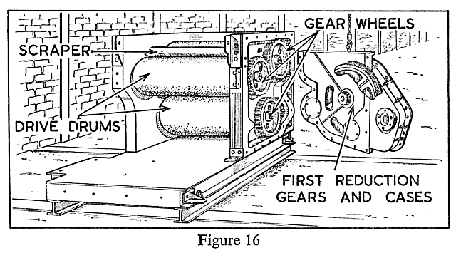
(c) Using suitable lifting tackle, raise and support the driving drum(s) in position. Place the top drum in position first, using a strong manilla rope as a sling (Figure 14).
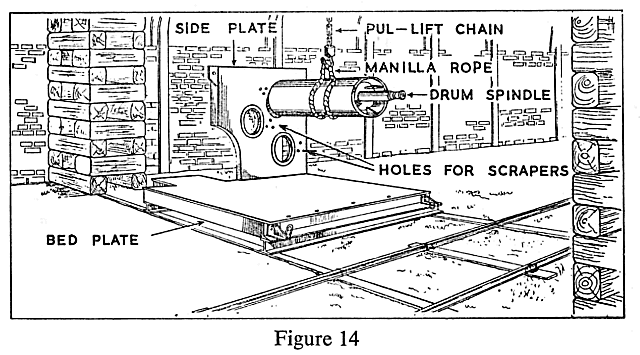
Sling the second drum into position and then roll the bottom drum on to the bed girders and raise it into its position. Bolt the drum scrapers into position.
(d) Erect and bolt in position the other side plate.
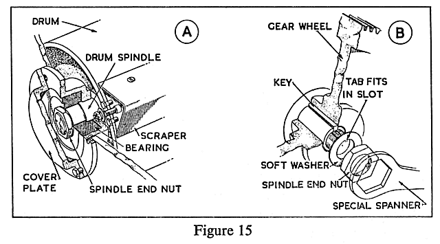
(e) Line up the drum spindles in the housings and fit the bearings on to the spindles. When the bearings are fixed, screw on the spindle end nuts and washers (Figure 15A).
(f) To the second side plate, bolt the drum scrapers.
(g) Bolt the back plate into position between the two side plates.
(h) Place the gear wheels on the extensions of the drum spindles, tightening them with a washer and nut, as shown in Figure 15B.
(i) On the side opposite to the gears pack the cover plates with grease and bolt them into position.
(j) Sling the first reduction gear into position; dowels attached to the framework enable the gearcase to be accurately positioned. Bolt into position (Figure 16).
3. Check that the driving drums are perfectly level.
4. Clamp the driving gear baseplate to the bed girders (Figure 13, inset C).
5. To prevent the slightest movement of the driving gears, secure the bed girders in their position by brickwork or concrete or by dowels driven into holes drilled into the floor.
6. Thread a length of belting round the driving drums.
| Note: |
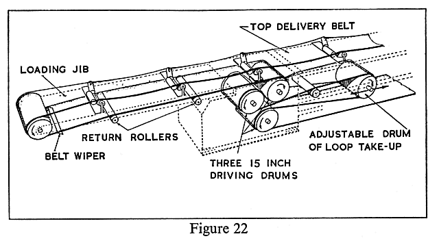
It is most convenient to do this at this stage. Figure 22 shows how the belt should be threaded where the drive contains three driving drums.
|
7. Attach the cover plate and idlers to the top of the drive structure.
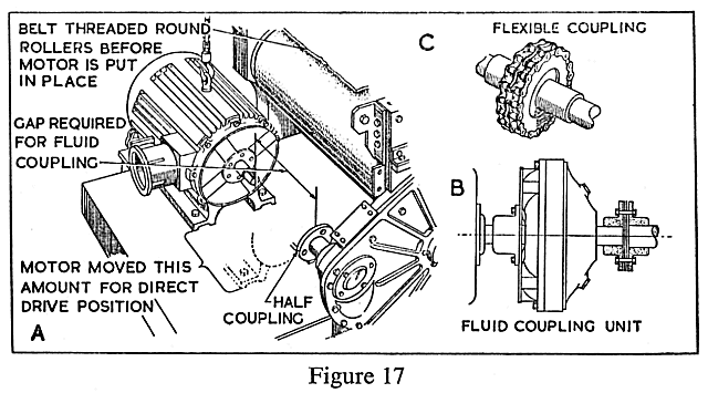
8. Place the motor in position and secure (Figure 17A).
| Note: |
There will be either a fluid coupling unit (Figure 17B) or a flexible coupling (Figure 17C) between the motor and the first reduction gear. It is very important whichever is used to see that the coupling is perfectly aligned. If not, vibration, rapid wear and heating of the bearings will result.
|
9. Connect the motor to the gate end box, with a length of pliable armoured cable tidily and safely positioned, care being taken that the power cannot accidentally be switched on while work is being performed on the conveyor.
Installing the Jib Head Structure
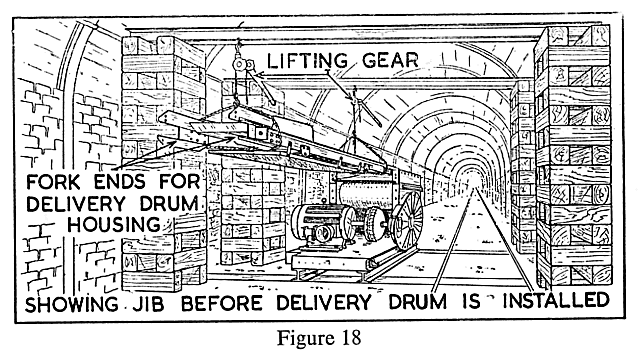
1. Build up the sections making the jib head (Figure 18).
| Note: |
The sections of the jib head are generally suspended from the roof supports as shown in Figure 3. Various kinds of suspension may be employed, but it is advisable that they should be rigid, and also adjustable in case the roof lowers.
|
2. Bolt the delivery drum assembly to the end of the jib.
3. Place side guards in position.
4. Check the alignment of the jib head by means of the plumb bob and the roof line or wire (Figure 19).
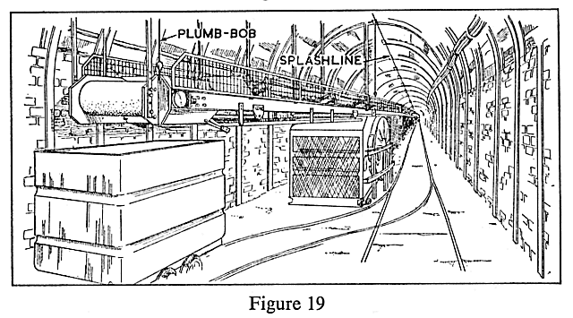
5. With a spirit level, check that the structure, especially the delivery drum, is level across.
Installing the Loop Take-up
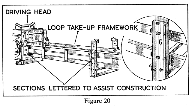
1. From the drive, build up the sections of the structure making up the loop take-up (Figure 20).
| Note: |
It is usual for this structure to be numbered so that each of the sections can be quickly mated.
|
2. Insert the movable roller and carriage between the structure (Figure 4).
3. Assemble the ratchet device in the position appropriate to the type of structure. Attach the rope or chains from the ratchet device to the carriage.
4. Attach the cover pans and idlers to support the top belt.
5. Check the alignment of the structure.
6. Place a spirit level across the pans and level up the structure.
| Note: |
No inflammable material must be used as packing pieces.
|
Installing the Belt
1. Prepare the ends of the length of belting (Figure 21).
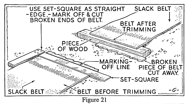
2. Attach the fasteners.
3. Trim the corners about ¾" from each edge. This prevents the edges of the belt from catching any projecting or damaged structure and so being torn.
4. The length of belting previously placed round the driving drums (page 11, paragraph 6) should be threaded round the jib head and loop take-up structure as shown in Figure 22.
5. Connect another length of belting to the end that has been passed round the loop take-up and roll this new length out along the gateway. This will form the bottom belt of the conveyor.
Installing the Intermediate Structure
1. Place the stools at distances apart equal to the length of the intermediate structure; the rollers assembled with the stool should be placed under the belt (Figure 23).
| Note: |
It is usual to have the stools raised from the floor on brick or concrete blocks. Special stools may now be obtained with long legs which raise the sections sufficiently. Dust or coal that is spilt from the conveyor can then be easily shovelled back on to the belt.
|
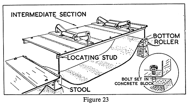
2. To the stools attach or bolt as required the cover pans or louvres (side plate open type).
3. Fit the sets of top idlers in position.
4. Align the structure, using a plumb bob (Figure 24).
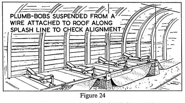
5. Level up the structure, using a spirit level placed across the pans.
| Note: |
Avoid the use of inflammable material for packing up the structure.
|
6. Connect lengths of belting to the end laid out on the jib head structure and roll out on top of the intermediate structure.
Installing the Return Drum
1. Pull the return drum into position and align correctly.
2. Thread the length of belting laid out in the gateway through the return drum structure, making sure that the belt is threaded over the bottom roller and under the plough. Use a length of soft iron wire to facilitate threading.
3. Connect up the return drum structure to the intermediate structure using a telescopic pan.
| Note: |
This allows the return drum to be drawn back and still remain in contact with the main structure of the conveyor.
|
4. Roll out and connect the lengths of belting on top of the intermediate structure. Connect these lengths to the piece passed round the return drum. The whole belt is now joined into one endless belt.
Signalling and Fences
1. Install a signalling system along the full length of the conveyor, and make sure that all fences are in position, before the belt is run.
Applying Tension to the Belt
(A) If there is no loop take-up:
1. Set up two anchor props, or drive two dowel pins into the floor, one on either side of the drum (Figure 25).
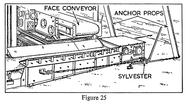
2. Pass the short chain from the Sylvester sword round the foot of the anchor props or dowels.
3. Attach the two long chains from the return drums to the sylvesters, one at each side.
4. Operate the sylvester levers to draw the return drum back, thus applying tension to the belt.
| Note: |
(a) Too great a belt tension may result in frequent belt breakages.
|
|
|
(b) It will be necessary to switch on the power to find out if the correct amount of tension is applied. Before switching on care should be taken to ensure that all guards are secured in position.
|
||
|
(c) New conveyor belt stretches; it is thus necessary to re-tension the belt at frequent intervals during the first two or three days of its use.
|
||
5. It is advisable to secure the return drum by chains direct to the anchor props or dowel pins. If the sylvesters are left to hold the return drum they may accidentally be knocked off.
6. Ensure that the belt will run centrally on the return drum — the final adjustments for central running are more easily made where adjusting screws are attached.
(B) Where there is a loop take-up:
1. Set up anchor props or dowel pins and secure the return drum in required position.
2. Operate the ratchet device on the loop take-up and apply tension to the belt. Initial tension may be obtained with the ratchet handle in the direct pull position; final tensioning is obtained with the handle in the geared position (Figure 26).
| Note: |
It may be necessary to run the belt to obtain slack belt to ease the pull in tensioning. Before switching on the power, make sure that no person is working in a position that would be dangerous to him if the belt were to move.
|
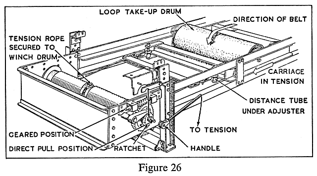
3. Ensure that the belt runs centrally on the loop take-up drum and the return drum.


 |
 |
 |
||

Back |

Home |
Copyright © 1999-2012 by The Durham Mining Museum and its contributors
Page last updated: 01 Jan 2008 |

Search |

|