


Mail: Webmaster

|

|

|

|
|
 |
 |
|||
Chapter I
General Description
 A Gate Belt Conveyor is a mechanical device which gathers the coal as it leaves the Face Conveyors and transports it along the roadway to some loading point where it is discharged into tubs or on to a Trunk Belt Conveyor.
The Conveyor consists essentially of four main parts:
(a) The Drive Unit or Gearhead.
(b) The Belt.
(c) The Intermediate Structure.
(d) The Return Drum.
Parts sometimes added are:
(e) Jib or Delivery Head.
(f) Loop Take-up.
The Drive Unit
This consists of a metal framework (Figure 1) containing the motor, gears and the belt driving drums.
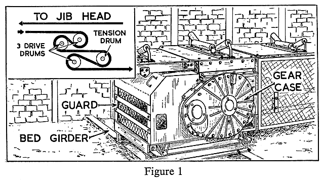
The motor may be either of the compressed air or electric type, with a range of horse-power from 15-200, electric motors being usual for the higher ranges.
There are usually two driving drums, the sizes of which may vary with the design. On some machines three drums are included. The drums may be 'lagged' with rubber to assist the grip of the belt, and they may be cambered slightly to help the belt to run centrally as it passes round the drums. The belt is made to move by the friction or grip between itself and the surfaces of the driving drums, as shown in Figure 1 inset. The drums are therefore placed so as to ensure that there is the maximum amount of belt wrap, thus providing the greatest driving effort between the belt and the drums.
To ensure that the belt surfaces are kept clean, scrapers are often attached to the drive structure. The drive is enclosed by guards to protect the workmen from moving machinery. These must not be removed unless the conveyor is stationery and they must be replaced before the conveyor is started.
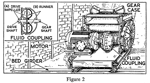
On some of the higher horse-power conveyors what is known as a fluid coupling is employed to connect the motor to the gears. As shown in Figure 2, the coupling consists of one impeller [(A) inset] which is attached to the drive shaft from the motor, and a runner [(B) inset] attached to the shaft from the gears. The whole is enclosed in a casing into which a light oil is added. The motor drives the impeller which, by movement of the oil, drives the runner, which in turn causes the driving drums to rotate. One of the advantages of using a fluid coupling is that, on starting, the load is picked up gradually and smoothly. Snatching and surging are also largely eliminated and belt life is thereby increased. Troubles with belt fasteners are reduced.
The Jib or Delivery Head
This is an extension from the drive to the delivery point (Figure 3) and may be made up to any length by the addition of extra intermediate jib sections.
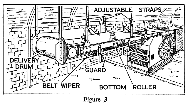
Guards are fitted to the framework to prevent the workmen from coming into contact with moving parts, especially the bottom rollers under the structure.
The Loop Take-up
This is often fitted to gate conveyors to enable a slack belt to be tightened and to 'store' belt so that the conveyor can be extended without the need to insert short lengths of belting.
It consists in the main of a sliding carriage containing a drum, the carriage being pulled along the framework by means of either a rachet and chain or, in recent types, a winch and ropes (Figure 4).
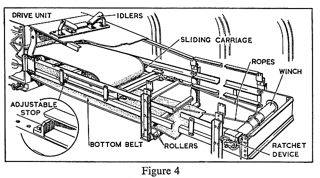
The drum may have a screw adjustment on each side to enable it to be correctly aligned.
Adjustable stops or gluts may be attached to the framework to hold the sliding drum in position and to prevent the carriage from being pulled back should the ropes from the winch break. Fences or guards are put round this structure for the safety of the workmen.
The Belt
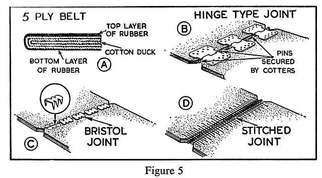
Conveyor belting is made of layers, or plies, of woven cotton (cotton duck) which have been impregnated with rubber. These layers are enclosed in a rubber cover. It is the cotton duck that enables the belt to withstand the tension. The rubber protects the cotton from damage (Figure 5, inset A).
| Note: |
The surface of the belt on which the coal falls tends to be cut and worn by sharp pieces of coal and stone. An extra thickness of rubber is applied to this side for protection of the cotton, and this side is usually marked in some way for identification.
|
A new type of belt made of non-inflammable material is now in use.
Belting is sent underground in rolls of such size that they can be handled easily. When assembled on the conveyor, the lengths of belting are joined together by fasteners, of which there are various types (Figure 5). The joints on some of the larger conveyors are now made by vulcanising in the pit.
The width of belt used depends on several factors, particularly the amount and size of coal to be carried. The normal widths for gate conveyors are 26" and 30", but in some cases may be 36" or as much as 42".
Intermediate Structure
This consists in the main of a framework which carries the sets of idlers which support the top and bottom belts (Figure 6).
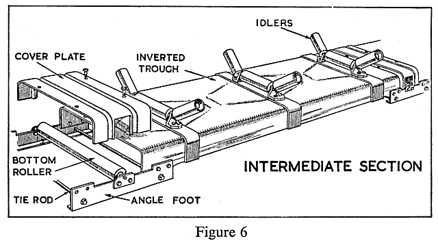
The idlers for the top belt are usually in sets of three or, in some cases, five, the outer rollers being usually inclined in order to trough the belt. The outer rollers may also be set with a slight lead in the direction of the gearhead to make the belt run centrally on the idlers.
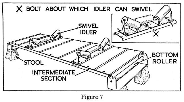
On certain types of conveyor, some of the brackets which carry the top idlers can swivel. This helps to keep the belt running centrally (Figure 7).
Return Drum
The return drum assembly consists of a box-like structure containing the drum around which the belt passes (Figure 8).
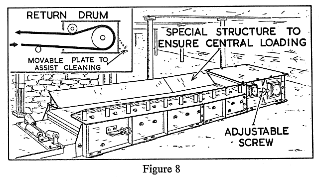
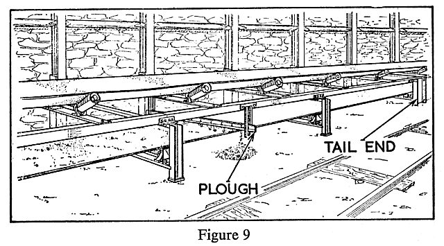
The drums may be of the plain type or of the self-cleaning type. It is usual for the drums to have screw adjustments to allow for final centring of the belt on the drum. A plough is usually incorporated within the structure to prevent anything that is being carried along by the bottom belt fouling the drum (Figure 9).
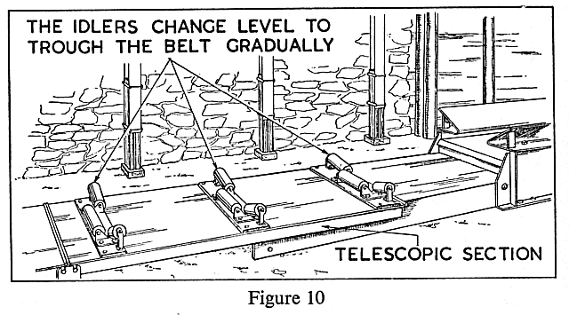
It is usual to have a telescopic section inserted between the return drum and the intermediate structure. This ensures a continuity of structure between them, whatever the position of the return drum (Figure 10).


 |
 |
 |
||

Back |

Home |
Copyright © 1999-2012 by The Durham Mining Museum and its contributors
Page last updated: 01 Jan 2008 |

Search |

|