


Mail: Webmaster

|

|

|

|
|
 |
 |
|||
Chapter II
The Setting of Props
How to Set a Prop
| Materials and Tools required :— | |
| Prop (wood or steel) | |
| Lid | |
| Hammer (5 lbs to 7 lbs in weight) | |
| Pick | |
| Saw | |
| Hatchet (in some Collieries). | |
 1. Choose the position where the prop is to be set. It may be in a row with other props, in which case its position will be determined by its distance from the other props in the row, or it may have to support some special part of the roof. Avoid, if possible, setting the prop under a break or cavity in the roof.
2. Test the roof by tapping it lightly with a hammer or pick at the same time touching the roof with the fingers. A drum-like sound or vibration indicates that the roof is broken, and special care must be taken in setting the prop. Pull down any loose stones before setting the prop.
3. Check the prop for length, which should be such that the lid cannot quite be placed between the prop and the roof in the position they will occupy, without the use of the hammer.
Note: A wood prop may be sawn to the correct length, but if the prop is tapered at one end, the opposite end should be sawn. Should a steel prop be too long, a hole should be made in the floor with the pick to provide sufficient clearance.
4. Place the foot of the prop in position. This can be found by dropping a piece of coal or stone from the position that the top of the prop will occupy and noting the place where it drops on the floor. In inclined seams the foot of the prop must be placed slightly "uphill" from the place where the stone hits the floor by an amount which will depend on the conditions at the face. Force the head of the prop, with the lid on top, firmly against the roof (Figure 17).
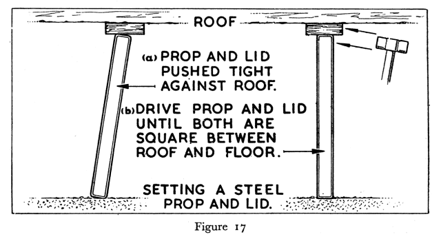
5. Hammer the prop and lid until the prop is tightly set.
Notes: In general the prop when set should be square with the roof and the floor.
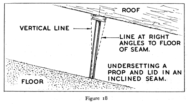
It might be desirable in inclined seams to underset the prop slightly as shown in Figure 18 because in some seams the roof tends to move in the direction of the dip. Movement like this would tighten a prop that was slightly underset but would slacken one that was set square.
Where a steel prop fitted with a wedge is used, the prop, with the lid, should be placed between the roof and floor with the wedge in the release position. The prop is then tightened by hammering the wedge.
How to Set a Bar
| Materials and Tools required :— | |
| Props | |
| Lids | |
| Bar or Strap | |
| Hammer | |
| Pick | |
| Saw | |
| Hatchet (in some Collieries). | |
1. Select the place where the bar is to be set, test the roof, and check the props for length as described in the setting of a prop.
2. Lift the bar to its place at the roof and hold it there. It may be necessary to hold it by means of a jack prop (Figure 19), and it may be necessary to have the assistance of another worker.
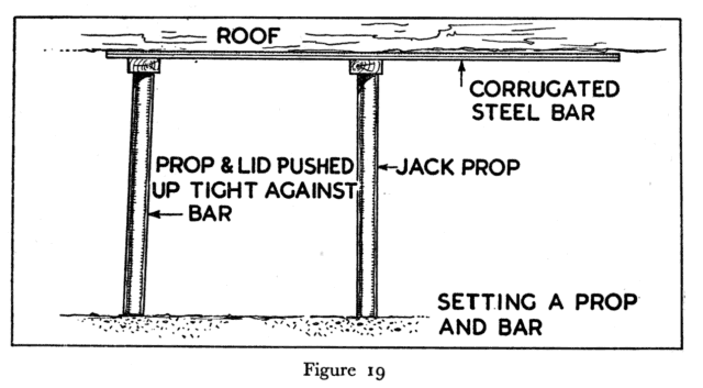
3. Push a prop, with a lid, if one is to be used, into position at one end of the bar and hammer it until it is tight (Figure 19).
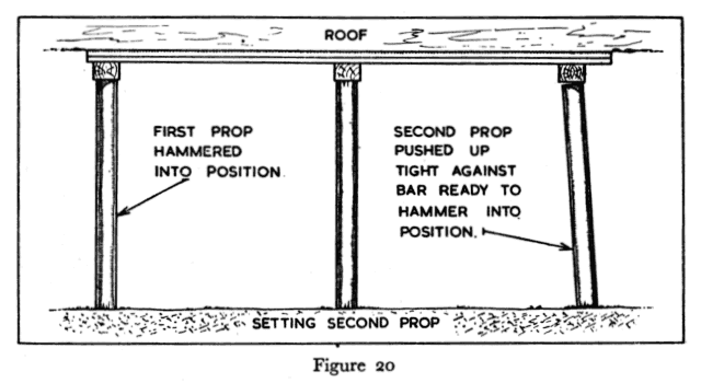
4. Do the same at the other end (Figure 20).
Notes: The broadest surface of the bar should be placed next to the roof.
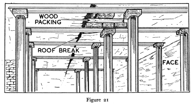
Avoid if possible setting the props under cavities as to do so increases the likelihood of damage to the bar. Where a prop must be set beneath a cavity, the cavity must be packed with wood lids above the bar before the prop is finally tightened (Figure 21).
1. All props should be set tightly with lids of adequate size.
2. They should be set directly on the floor of the seam, but if the floor is soft, a wood foot-piece of suitable size [Figure 3(b)] should be used to prevent the foot of the prop being pushed into the floor.
3. It is bad practice to mix wood and steel props on the same face as this leads to unequal loading of the props and may cause bad roof conditions.
4. Avoid setting props under cavities.
Setting Holing Sprags (or Nogs)
| Materials and Tools required :— | |
| Cutting Nogs | |
| Hammer | |
| Shovel | |
| Pick | |
1. Clear the gummings or cuttings from the place where the nog is to be placed so that it will not rest on loose material.
2. Insert the nog into the cut and drive it in tightly with the hammer.
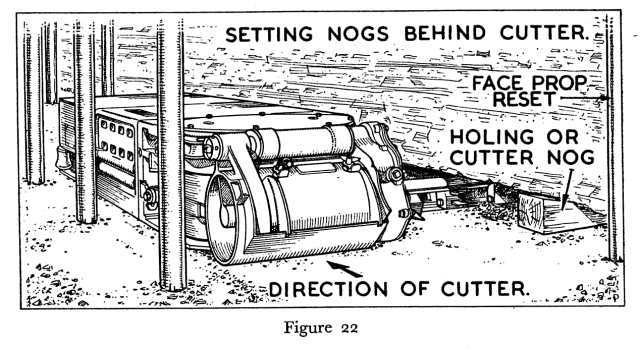
Notes: The nogs should be inserted as close behind the cutting machine as is practicable and the distances between the nogs should not be more than 6 feet. (Figure 22).
Whilst setting nogs care should be taken to avoid being hit by any coal that may fall from the front of the coal face.
Building a Chock
| Materials and Tools required :— | |
| Hardwood Chock Pieces (including two which are of half thickness and also two soft wood pieces). | |
| Note: Round section chock pieces are not permitted except in chocks which are to be left in the packs or waste because, owing to their shape, they become crushed without offering sufficient resistance. | |
| Wedges | |
| Two Chock Releases (if these are to be built into the chock) | |
| Hammer | |
| Pick | |
| Shovel. | |
1. Clear the floor at the place where the chock is to be set.
2. Build the chock as shown in Figure 23.
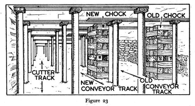
Notes: It is good practice to place the two bottom pieces of the chock at right angles to the face so that they may be more easily recovered when the chock has been dismantled.
When chock release devices are used, they are put into the chock about half way up. They should be placed parallel to the face, so that the release catches can be operated on each side from safe positions when the chock is being withdrawn.
The chock pieces of half thickness are useful to complete the chock at the roof where there is not room for pieces of full thickness.
The wedges which are used for tightening the chock are placed below the top pieces so that the latter give support to the roof over the whole of their length.
IMPORTANT POINTS
1. Chocks should not be set on loose dirt but should be built on the floor of the seam. Chocks set on loose dirt offer little resistance to subsidence, as they crush into the soft foundation.
2. A chock must be wedged tightly between the roof and floor so that it gives immediate support to the roof.
3. Each piece should be placed directly over the one below as shown in Figure 23.
The Building of Packs
| Tools required:— | |
| Shovel | |
| Hammer | |
| Pick | |
| Long-handled Rake | |
| Sylvester. | |
1. On the roof draw a line to which the outer walls are to be built. Those at the side will be extensions of the side walls of the previous pack.
Note: Better results are obtained if packs are built in sections, in the way that is described later. By this method the material is kept tighter within the pack and the cross walls increase the strength.
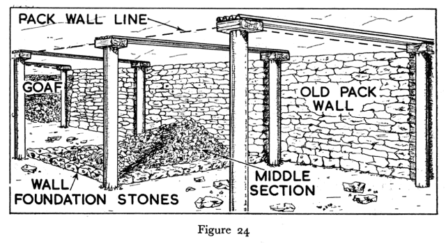
2. Clean up the floor for the pack wall foundation stones of the first section; lay the stones with their lengths pointing into the pack. Throw in small dirt up to the level of the top of the foundation stones (Figure 24).
3. Spread the small dirt on top of the foundation stones to act as "bedding" or mortar for the next layer of wall stones. Put on the next layer of wall stones, crossing the joints of those below. Again fill in with loose dirt allowing some to act as bedding for the next layer of walling stones. Continue this until the section is built to the roof (Figure 25).
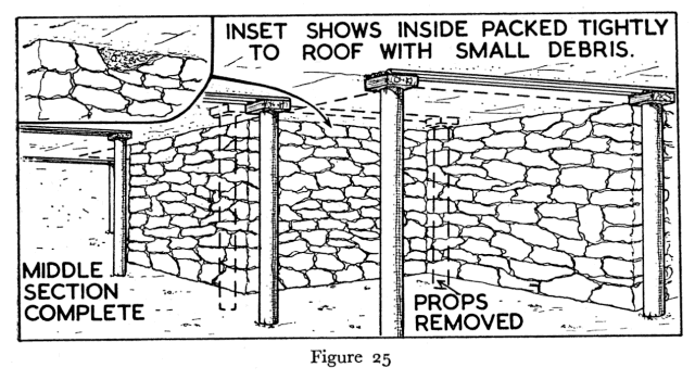
Note: The debris must be rammed tightly to the roof before the walls of the pack are completed so that the pack as a whole and not only the walls support the roof.
4. Set temporary props and remove the supports (for removal of supports see page 29) to enable the next section of the pack to be built.
5. Build up the remaining sections as described in operations 2 and 3 (Figure 26).
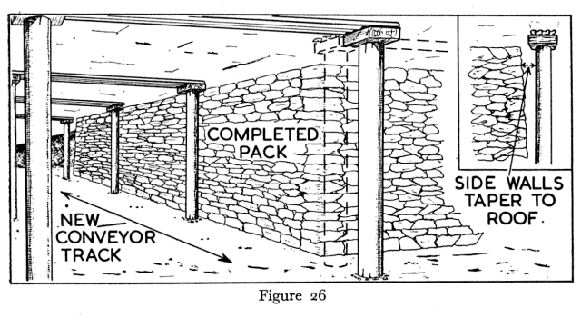
Note: In level or nearly level seams it is good practice to slope the outer walls of the pack inwards towards the top by about 1 inch for every foot in height. This reduces the likelihood of the walls bulging outwards and collapsing under pressure (Figure 26 inset). The amount of slope, if any, in inclined seams depends on local conditions.
IMPORTANT POINTS IN BUILDING PACKS
1. The material inside the pack should be rammed tightly to the roof before the final stones of the wall are placed in position.
2. Small dirt should be placed between all the stones of the wall to act as bedding. This greatly increases the strength and stability of the pack.
3. The best stones available should be used in building the walls, particularly the side walls.
4. The stones used for building the walls should be arranged with their lengths pointing into the pack.
5. The long-handled rake should be used to reach any material needed for the pack that is under unsupported roof in the waste.
The Arrangement of Supports at the Roadhead
It is necessary to have a system of supports in the region where the roadway joins the coalface that allows sufficient space for the machinery that is located there. This is obtained by using long bars, equal in length to the width of the roadway, to support the face bars. These long bars are often called carrying bars, and a typical arrangement is shown in Figure 27.
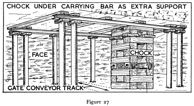
The sequence of operations in setting the supports is as follows:—
1. Set temporary props under the face bars and remove one row of props from under the ends of the bars (Figure 28).
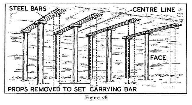
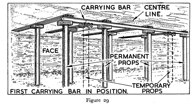
2. Set the first carrying bar under the ends of the face bars and support it first of all by temporary props. Then set permanent props under this bar and remove temporary props (Figure 29).
Note: Place lids between any two steel supports, e.g., between steel props and steel bars, or between two steel bars.
3. Set a second carrying bar under the other end of the face bars and remove the temporary props from beneath the carrying and face bars (Figure 30).
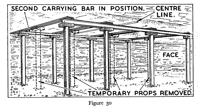
Note: There should be one of the carrying bars as near as practicable to the edge of the ripping.
These carrying bars support large areas of roof under which men are constantly passing. It is desirable, therefore, to set two props under each end of the carrying bars and, if there is room, a chock under the middle to increase the stability of the system.
The Arrangement of Supports at the Ends of the Face
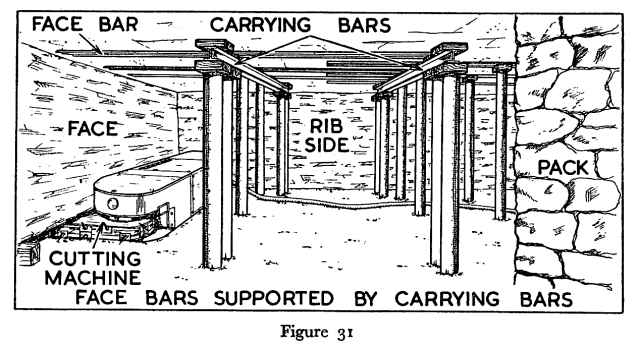
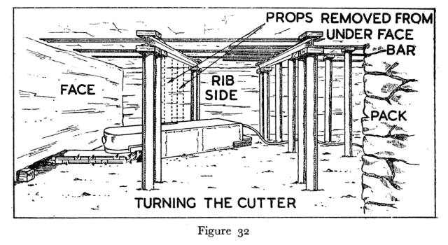
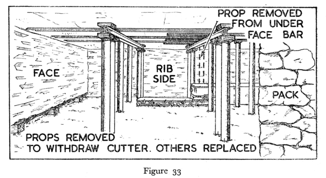
Supports at the ends of the face have to be arranged so that the coal cutting machine can be turned round without removing the face bars. This is done by supporting them by long carrying bars. A typical arrangement is shown in Figure 31.
Props are removed one by one during the turning of the machine and are replaced immediately afterwards, as shown in Figures 32 and 33.


 |
 |
 |
||

Back |

Home |
Copyright © 1999-2012 by The Durham Mining Museum and its contributors
Page last updated: 01 Jan 2008 |

Search |

|