


Mail: Webmaster

|

|

|

|
|
 |
 |
|||
Chapter I
General Description and Arrangement of Face Supports
 Coal is the natural support of the rocks that lie above the coal seam. When the coal is extracted, those rocks tend to lower into the space previously occupied by the coal and to break. Supports have to be set to control the roof movement, to prevent as far as possible the formation of breaks, and to ensure the safety of the workmen. The various types of supports are called props, bars or straps, holing nogs, sprags, chocks and packs.
DESCRIPTION OF SUPPORTS
Props
Props may be made of wood or steel. Those that are made of wood are cut from trees of Spruce or Fir, and are of circular section as shown in Figure 1.
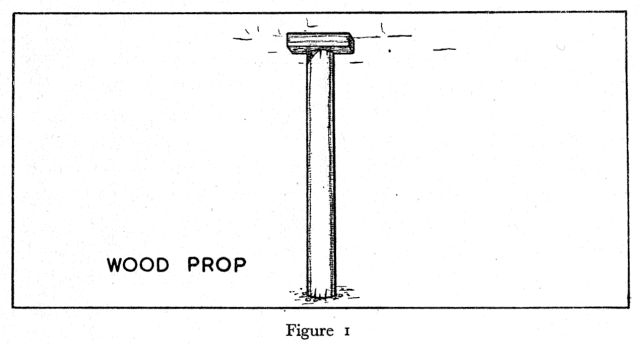
Experience has shown that as a general rule the diameter of a wood prop should be 1 inch for every foot length of the prop, so that a prop 4 feet long would be 4 inches in diameter. A good wood prop of these dimensions will support a load of approximately 20 tons before breaking. Props of diameter less than 2½ inches are never used, however, even in the thinnest seams.
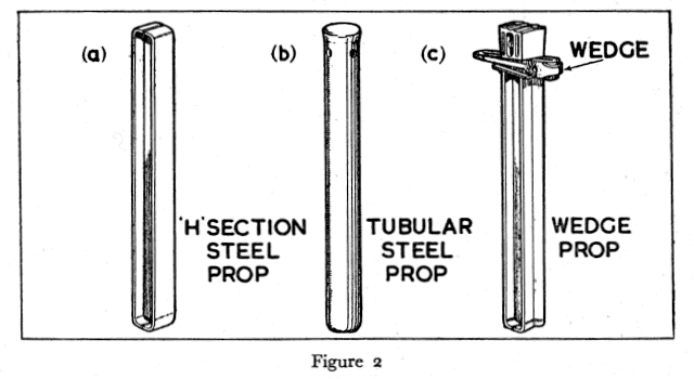
The most common type of steel prop used in this country has an ‘H’ section [Figure 2(a)]. Another type less frequently used is tubular in shape [Figure 2(b)]. Tubular props may sometimes be filled with wood. Many steel props are fitted with special heads each incorporating a steel wedge which makes it easier to set the prop [Figure 2(c)].
Steel props have many advantages over wooden ones. They are stronger and are also more uniform in their strength. An ‘H’ section prop, 4 feet long and 4 inches by 4 inches in section will withstand a load of approximately 65 tons, a figure which should be compared with the 20 tons in the case of a 4 inch diameter wooden prop. Steel props are not damaged so easily as wooden props and can thus be used over and over again. Moreover a steel prop will continue to give some support even after it is bent, whereas a wooden prop once it is broken is useless as a support.
Lids
A lid is a piece of soft wood which is placed between a prop and the roof. It serves to spread the support which the prop offers to the roof over a wider area than the top of the prop itself. Moreover, because it is crushed more easily than the prop, it permits the roof to lower a little without damaging the prop. A lid must be big enough to cover the whole end of the prop above which it is set. One suitable for a prop 4 inches in diameter would be 8 inches to 12 inches long, 4 inches to 5 inches wide and 2 inches to 3 inches thick as shown in Figure 3 (a).
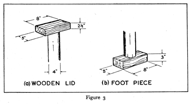
Wood lids should always be used between props and steel bars as they reduce the risk of damage to the props. They also reduce the risk of slip taking place between prop and bar where steel props and steel bars are used together.
Bars
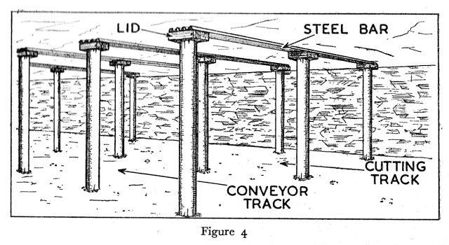
Bars may be of wood or steel and are generally from 4 feet 6 inches to 7 feet in length. They are set as shown in Figure 4 with two or more props to hold them to the roof. Compared with props and lids they are more stable, they support greater areas of roof and are in consequence more suitable for supporting broken roof.
Wood bars are generally made by sawing props lengthwise so that the bars are half round, but bars of rectangular section are sometimes used. Their widths and thicknesses vary but the average wood bar is 5 inches wide and 2½ inches thick (Figure 5).
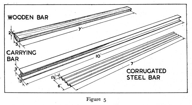
Steel bars have a corrugated section, so that their resistance to bending is greater than that of flat bars. They are not as easily damaged as wood bars; if bent they can be straightened and reset several times.
Steel bars of ‘H’ section or channel |¯| section may also be used, especially if the bars have to be long (Figure 5).
Long bars such as this are frequently used at road heads and at other special places:
Holing Nogs, Sprags and Stays
When a face is cut, specially shaped wedges of wood or steel are driven into the cut at regular intervals of not more than 6 feet to support the coal. These are called nogs or sprags (Figure 6).
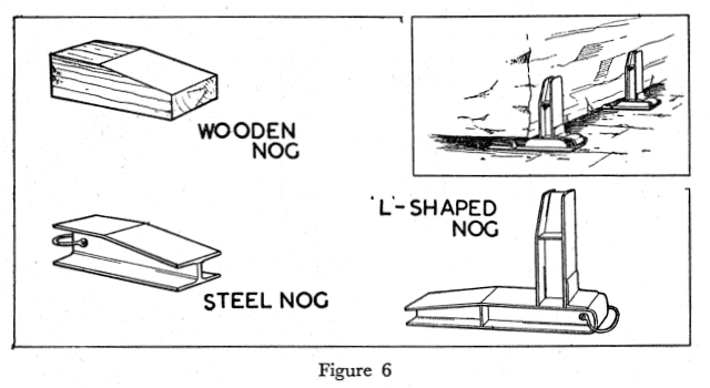
The ‘L’ shaped nog is sometimes used as it gives support to the front of the coal as well as to the bottom (Figure 6).
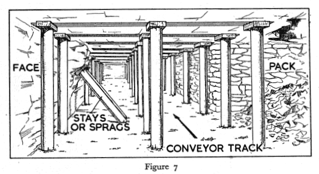
Supports must always be set to overhanging coal or stone. These supports are called sprags or stays (Figure 7).
Chocks
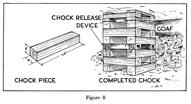
It is frequently necessary to provide stronger support to the roof than that which is offered by props. and bars. Chocks, which are both strong and stable are used for this purpose. They are generally built of pieces of hardwood, usually Beech or Oak about 2 feet long and 6 inches square .in section as shown in Figure 8.
Chocks may also be made partly of steel and partly of wood as shown in Figure 9.
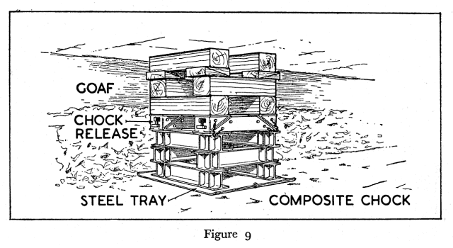
Special devices called chock releases should be incorporated in chocks so that they may be easily released when they are under the pressure of the roof at the time they have to be withdrawn.
Packs
The supports so far described are known as temporary supports, as they are withdrawn when the face is advanced. Packs, however, are permanent supports. They are built of stone collected from the waste, or from rippings (Figure 10). Stone is sometimes also sent into the district to be built into packs.
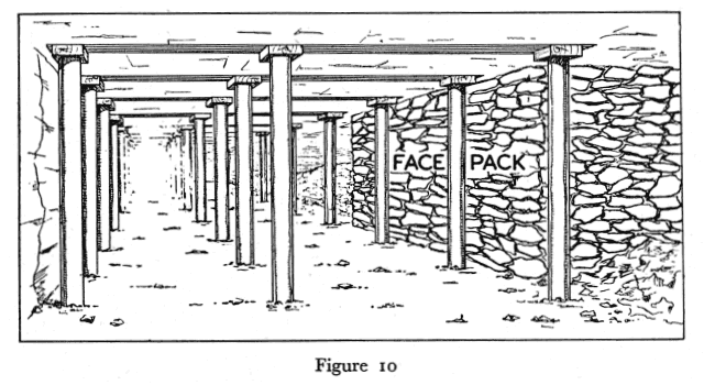
It is usual for packs to be built in continuous strips, a system which is called "strip packing”. The packs are usually 3 to 6 yards wide and extend from the face props back into the waste. They are spaced 5 to 15 yards apart along the face. The rocks of the roof between the packs and behind the temporary supports are allowed to collapse.
At some faces all the goaf or waste is filled with debris; this is known as "solid packing".
At other faces no intermediate packs are used between the main gate and tail gate packs, the roof behind the face supports being allowed to collapse. This is known as caving
Most packs are built by hand, but some are built by the method known as "pneumatic packing". In this method crushed rock is blown by compressed air through pipes into the place to be packed.
THE ARRANGEMENT OF THE SUPPORTS ON THE COAL FACE
There are two main systems of working coal in Britain, namely, "Longwall" and "Pillar and Stall."
Longwall
In Longwall workings, the coal is extracted from faces which are, as a rule, up to 200 yards long, but which may be even longer. The supports are usually arranged as shown in Figure 11.
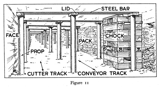
The props are set in rows, the distance between the rows and between the props in the same row being specified by the Manager according to the rules laid down in the Coal Mines Act and to his knowledge of what is required to maintain good roof conditions. The distance between the rows is often up to 4 feet, but where bars are used it may be increased to 6 feet. The distance between the props in the same row is up to 4 feet. According to regulations these distances must not be exceeded.
Chocks are set as a rule opposite the waste areas on the goaf side of the conveyor, their distances apart, also, being laid down by the Manager. At some collieries, however, the chocks are set on the face side of the conveyor before it is "flitted" over into the new track.
Cycle of Operations
The work on the coal face is performed in a regular sequence called the "cycle of operations" which is normally spread over three shifts in twenty-four hours. A typical 24 hour cycle is as follows:—
First Shift
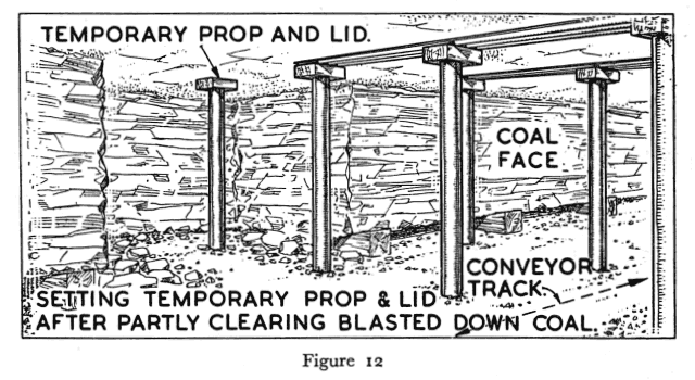
The coal cut in the previous shift is filled on to the conveyor, and as the coal is removed, temporary props are erected (Figure 12) — until there is room for a prop and bar (Figure 13).
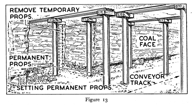
There must not be more than 3 feet of clear ground before a temporary prop is set. When the whole of the face has been cleared of coal, there will be a new row of props and bars supporting the roof along the whole length of the face.
Second Shift
The face conveyor is dismantled and re-erected in the new track, the chocks are built and the packs are extended. The props and bars and the chocks at the waste edge are withdrawn and are stacked in a convenient place ready for re-setting. The withdrawal of these supports allows the roof at the waste edge to fall.
Third Shift
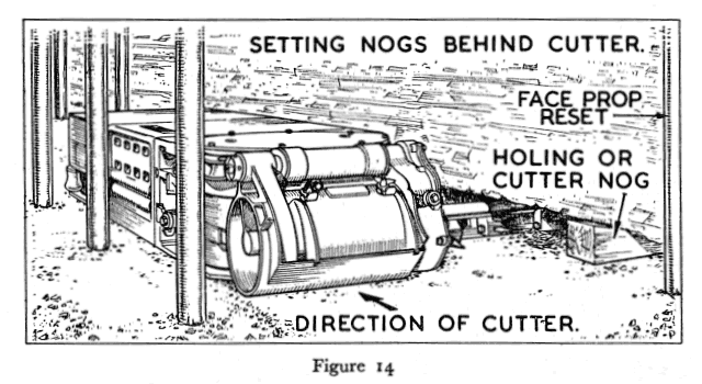
In this shift the coal is cut and the cutting nogs or sprags are inserted into the cut immediately behind the machine as it moves along the face (Figure 14).
Pillar and Stall
In pillar and stall workings, the coal is extracted by driving headings and cross headings leaving blocks of coal to support the roof. These blocks are known as Pillars and are extracted later.
In this method of working the coal is cut and filled as required.
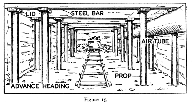
In the headings or stalls the roof is supported by rows of props and bars. One arrangement is shown in Figure 15.
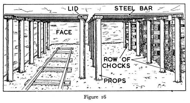
The coal from the pillars may be extracted by different methods. The usual way is to keep taking strips or lifts about 4 yards wide off the pillar to work out the coal. In the lifts the roof is supported by rows of props and bars, additional support being given by rows of chocks, at the waste edge, as shown in Figure 16.


 |
 |
 |
||

Back |

Home |
Copyright © 1999-2012 by The Durham Mining Museum and its contributors
Page last updated: 01 Jan 2008 |

Search |

|