


|

|

|

|
|
 |
 |
 |
||
I. Description Of The Colliery And Method Of Working.
The Hulton Colliery is situated close to Atherton, about eleven miles to the west of Manchester, and it really comprises four distinct collieries. The number of coal drawing shafts is seven, and, prior to the accident, about 2,400 tons of coal were raised per day. The total number of persons employed at the surface and below ground was about 2,400.
The pit commonly known as the Pretoria pit constitutes one of the separate groups. The Nos. 3 and 4 shafts, which were sunk in the years 1900 and 1901, are each 18 feet in diameter, and placed 75 yards apart. No. 4 s the downcast shaft and No. 3 the upcast shaft. Both shafts are sunk to the Arley mine* or seam, which lies at a depth of 434 yards from the surface. There are five seams being worked from the two shafts, namely, in order of depth
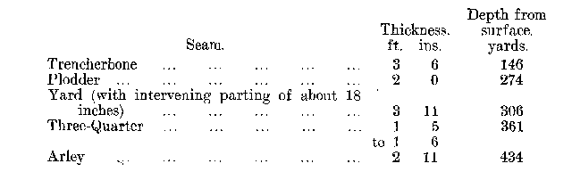
The general dip of the seams is to the south at an average inclination of 1 in 5.5.
A large fault, traversing the mineral tract worked from the Nos. 3 and 4 [Bank Pit] shafts, east and west, and another almost at right angles to the same (see Plan, I.) have conduced to an arrangement of cross-measure drifts and coal roads, which allow of three seams being worked from one level in the No. 3 shaft, viz., the Plodder, Three-Quarters, and Yard seams; and it was in this level that the explosion occurred. There are five main workings or divisions in this level known, respectively, as the North Plodder, the Three-Quarters, the Top Yard (or Up Brow), the Bottom Yard (or Down Brow), and the South Plodder.
The five main divisions were further divided into the following districts
1. North Plodder (No. 1 Face, No. 2 Face). (North Plodder old workings not being worked).
2. Three-Quarters.
3. Top Yard.
4. South Plodder. (South Plodder old workings not being worked.)
5. Bottom Yard (East Jig District, and Down Brow District).
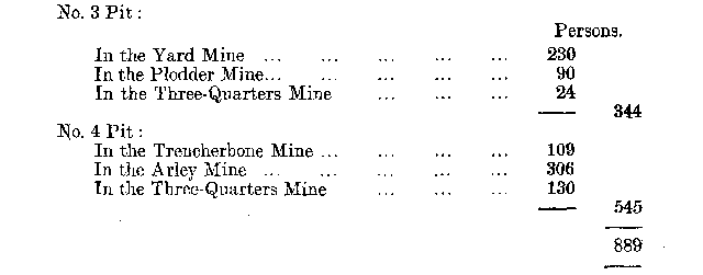
The most extensive of the divisions were the Top and Bottom Yard workings; the other districts were workings of smaller seams above and below the Yard seam and connected by drifts with it. Of the smaller districts, two were rise workings, namely, the North and South Plodder districts. The Three Quarters was a small dip district, employing few men; but in the North Plodder-the highest district in the No. 3 pit-about 70 men were employed. The coal in all these districts was worked by the Longwall system. The total number of persons working in the No. 3 pit on the day of the explosion was 344, and in the No. 4 pit 545, distributed as follows
* In Lancashire as in North Staffordshire the word "mine" is used to designate "seam."
The coal from the larger area of the Three-Quarter seam was brought to the Arley mine level and drawn to the surface at the No. 4 shaft. From a" mouthing" or "inset" in the No. 3 shaft at the Yard mine level, the coal from the Yard, Plodder, and a portion of the Three-Quarter (smaller area) was raised. The Trencherbone coal was raised from a "mouthing" in that seam in the No. 4 shaft.
(a) The System of Ventilation: (1) The Fans. — A large Sirocco fan, 8 feet 2 inches in diameter, with double inlet and capable of exhausting 300,000 cubic feet of air per minute from the mine at a 3-inch water gauge, was fixed at the surface of the upcast shaft. This fan, which was electrically driven, was used as a stand-by, being worked at week-ends when the underground fans were overhauled, or in the event of anything going wrong with the latter. The speed of this fan could only be varied by changing the pulley on the motor which drove it, the latter being a polyphase current induction motor running at a fixed speed.
When the present general manager came to Hulton Colliery, it was ventilated by two furnaces and steam jets; shortly after his appointment as manager ventilation by fan was adopted. He said in evidence: " Our seams, speaking generally, are very thin, and we required a fairly high water gauge. The fan that we put in first was put in to work between four and five inches of water gauge to give us the required amount of air. We found after starting it up that we were only getting one-half of the air underground that we were getting through the fan,"-pointing to heavy leakage from the surface into the fan chamber. The following particulars as to loss of air in the shafts were put in as evidence
At the Deep Arley pit, with the fan fixed on the surface, the water gauge was from 3 inches to 4 inches.
The actual amount of air coursing through the two working mines was less than 50 per cent. of the total amount of air passing through the fan.
At the Chequerbent pits, with the fan fixed on the surface, the water gauge was 2 1/6 inches, and at this water gauge fan was passing 105,850 cubic feet of air.
The actual amount of air passing in the mines, 72,870 cubic feet, or a loss of 31 per cent. This loss was afterwards reduced to 25 per cent.
The ventilation of the workings of the Nos. 3 and 4 pits was effected normally by four electrically driven Sirocco fans placed below ground. Three of these were exhausting and one a forcing fan.
The fans were placed: one in the Arley mine, another in the Three-Quarters, a third in the Yard mine, and a fourth in the Trencherbone. The forcing or compressive, fan was that which produced the ventilation in the No. 3 pit workings, and this means of ventilation was used instead of that by exhaustion, owing to the fact that the coal brought to the shaft at the Yard seam level was wound up at the Upcast shaft. It was for this reason that the haulage of the coal was carried on in the return airways of No. 3 mine. Had an exhausting fan been used it would have placed an obstruction in the "mouthing," and so have impeded the drawing of the coal. The fan was placed close to the downcast shaft (see Plan I.) sucking the air there from and forcing it round the workings.
(ii) The Volume and Measurements of the Air Currents. — The course followed by the separate air currents or splits in the No. 3 pit is indicated on the Plan, I., on which also are shown the positions of the doors, regulators, stoppings, and air crossings. The air crossings were built of brick, with wood tops laid on girders; the main road stoppings were substantially constructed of dirt (stone) packing, faced with brick walling, and the regulators were properly constructed wooden sliding doors.
The general manager gave it in evidence that the volumes of air circulating in the different seams at No. 3 and No. 4 pits at the date of the accident were about as follows
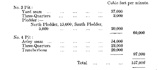
This would be at the rate of 174 cubic feet per man per minute in the No. 3 pit, and it should have been ample to meet the requirements of the mine if properly utilised.
The volumes of air mentioned above as circulating in each of the seams constituting the No. 3 pit are not taken from the statutory ventilation book of the mine, as the splits were not measured for each seam. The figures were put in by the general manager in evidence: those taken from the ventilation book shows the total quantity to be about 4,600 cubic feet less.
Only the three main splits were measured. In the North Plodder there are two faces separately ventilated from the main north intake, but the air currents ventilating these faces were not separately measured, only the total amount. Again, the Top Yard, the Three Quarters, and the South Plodder workings were ventilated by splits from a second main current, but these were not separately measured, only the total quantity. The third recorded measurement was for the Down Brow Yard and East Jig (Yard seam) districts, the latter being ventilated by the return air from the Down Brow district, and a scale of intake air from the East Level.
These measurements are given in the ventilation book of the No. 3 Pit, the last entry being for November 3rd, 1910 (the explosion happened on December 21st), the places of measurement being indicated only by the letters N., S., W., representing north, south, west. The record is as follows
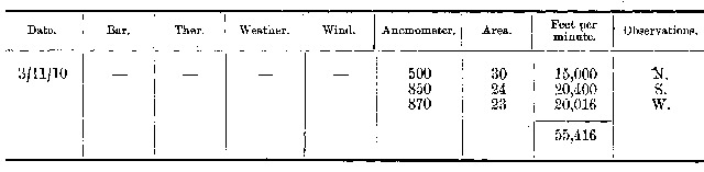
The points at which these three main splits were measured are shown on Plan I., and it will he seen that the measurements were made as near the shaft as possible, and therefore are not so reliable an indication of the amount of air traversing the workings as they might be, for some allowance must be made for leakage. I do not, however, think that the leakage would amount to very much, as the distance from the shaft to the workings was not great, and the air current at the faces when I inspected the mine on February 22nd, before its complete restoration, was very brisk.
The ventilation measurements were not made at regular intervals, the word "month" in General Rule 1, being interpreted as calendar month instead of every four weeks. Thus, I find for the year 1910 the records are entered as follows :-
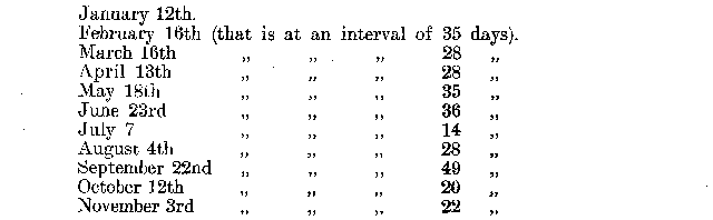
The actual places of measurement were not stated in the record book.


A copy of this report was kindly donated by
West Cumbria Mines Research.




 Contains public sector information licensed under the

