


| Newspaper Articles |

|
Newspaper Articles |
 |
 |
27th July 1940, Page: 26, Column: 1
Loading-Point Dust
South Wales Committee's Report
The Coal Dust Research Committee of the Monmouthshire and South Wales Coal Owners' Association was appointed to participate in a general investigation into the problem of the reduction of dust in underground workings, following the suggestion of the British Colliery Owners' Research Association. Dr. T. David Jones, Professor of Mining at Cardiff University College, was appointed Director of Research, the underground and laboratory investigators being Mr. W. A. Terrell, M.Sc, and Mr. J. Howard Griffiths, B.Sc, respectively. The first report of the Committee, representing the first eight months' work of the Research Laboratory fitted up in the Mining Department at the College, has been issued on "The Design and Testing of a Dust Collector for a Conveyor Loading Point in an Intake Roadway." The introduction to the report informs that the problem under consideration was the collection of the coal dust arising from a loading point as a whole and not merely that raised in the actual loading into the trams. Extracts from the Report are appended.
Dust Tests in Air-current.
A conveyor loading point is unquestionably the place where the greatest coal dust clouds are raised into the air-current in modern mining. The amount of dust raised into the air-current at the loader has been estimated to be about ten times as great as that produced at any other single point in the mine. Tests were carried out in the Seven Feet Seam at Bargoed Colliery to determine the amount of dust actually present in the air-current at and beyond a conveyor loading point, and further tests were carried out after the installation of the dust collector, in order to determine its efficiency.
To determine the amount of dust in the air-current passing the loading point, a series of samples of air-borne dust were taken, by drawing, by means of a hand-operated pump, a measured volume of the dust cloud through a Soxhlet thimble filter which retained the dust, but allowed the air to pass through. When taking dust samples by this method at such a place as a conveyor loading point, there are three variable factors which govern the amount of dust present in the air sampled. These are : (1) Tonnage of coal filled ; (2) Quantity of air sampled ; (3) Time of sampling. Each of these might be made constant as a basis for sampling, but as the amount of coal filled at the loader is the chief factor which governs the amount of dust raised into the air-current, it was decided to use a constant tonnage as a basis for all the sampling. In all the sampling tests both the times of sampling and the quantities of air passed through the filters, were recorded while a journey of 20 trams, of 22 cwt. each, were being filled at the loader.
The conveyor loader in the Seven Feet Seam at Bargoed Colliery is situated in an intake airway, and the sampling stations were selected at various points between the loader and the coal face.
Design of Dust Collector.
It is shown by graph that the amount of dust present per cubic foot of air passing the loader diminishes rapidly between the loader and a point about 80 feet on the inbye side. The dust problem is most acute, and visibility is very bad up to a point about 60 feet from the loader. Between a point 80 feet from the loader and the coal face, the curve is very flat, which shows that the dust present is so very line that it is capable of being carried along a considerable distance by the intake air-current.
If, instead of being dispersed throughout the whole area of the roadway, this dust was passed into a tube, then it is possible to induce the coarser dust up to a point 80 feet from the loader to settle out by normal gravity dry deposition, while the finer dust capable of being carried a greater distance than 80 feet might be allayed by wetting the dust particles in the tube by means of a mist projector or finely divided water spray. This is the principle of the dust extractor which has been designed and installed at the conveyor loader in the Seven Feet Seam at Bargoed Colliery.
Whereas a tube 80 feet in length may be considered as being impracticable in the mine, it is possible that a shorter length of tubing might be equally as effective if it is fitted with a system of baffle plates. Baffle plates produce turbulence of the dust-laden air, and act as buffers against which dust particles may strike and thereby have their momentum suddenly reduced so as to cause them to settle more quickly. By a suitable arrangement of baffle plates in the tube, it appears reasonable to suppose that the required length of 80 feet of tubing might be appreciably reduced and almost similar results obtained.
A dedusting apparatus incorporating these principles of dry deposition of the coarse dust and wet allayment of the line dust could be connected to the conveyor loader without in any way impeding the normal loading operations, and it was therefore decided to have such a dust collector made in the workshop at Bargoed Colliery, and, after a preliminary try out on the surface, to have it installed underground at the conveyor loading point in the Seven Feet Seam. The dust collector subsequently made at the Bargoed Colliery workshop is shown in the accompanying illustration.
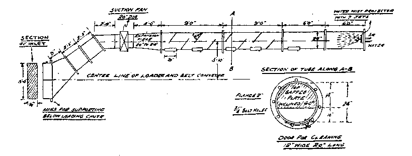
The suction end or inlet to the dust extractor, which is in the form of an expanded throat, fitting just below the lip of the loading chute, and also that portion of the apparatus from the throat up to the 20-inch diameter suction fan, were made according to the original design.
The dust trap made at Bargoed Colliery, however, did not follow the original design, and in place of a metal box of section 3 feet by 3 feet, use was made of some old 2-foot diameter ventilation tubes. Each of the circular tubes, 9 feet in length, has four baffle plates fixed in it, spaced at intervals of 2 feet apart. Below the baffle plates which are attached to the top of the tubes there are small doors for cleaning out the dust deposited on the bottom. The two tubes at the extreme end of the dust trap are each 6 feet long and they have no baffle plates fixed in them, so that the mist projector fixed in the outlet end can operate against the direction of the dust-laden air.
The spray or mist projector is operated by compressed air and water through jets. The water need only be at low pressure, and only a small quantity is required to make a very effective mist. The most efficient way of allaying the dust is to have the mist blowing in opposition to the direction of the dust-laden air, as every particle of dust is then more likely to be brought into intimate contact with a particle of water in the mist.
Several improvements were recommended as the result of a preliminary test, and when they had been completed the dust extractor was taken underground and erected at the "C" conveyor loading point in the Seven Feet Seam.
An important point which was given a good deal of consideration during the installation of the dust extractor was the manner in which the expanded throat could be attached to the loading chute, so that it would retain its correct position relative to the edge of the chute, and also to the tram standing at the loader. Subsequent work at Bargoed Colliery proved that for the dust extractor to give always the best results, it was necessary to have keen supervision to keep the track and loading chute in correct alignment relative to one another, as this greatly reduces the amount of dust which might escape around the sides of the inlet to the dust extractor.
The inlet tube is set about 6 inches above the top of the empty tram standing at the loader, a height that necessitates the inlet being fixed some distance away from the actual point where the coal leaves the edge of the chute to enter the tram, and in this distance some of the dust cloud becomes dispersed into the air-current and passes around the sides of the throat before it can be drawn into the tube. This difficulty was overcome by extending forward the sides of the expanded throat by means of small plates, while strips of old belting were hung loosely from the sides of these plates. When the dust extractor was then tried out under normal working conditions at the loader, the dust cloud made in the tram when loading could be clearly seen streamlining into the expanded throat of the inlet tube, while no dust was emerging from the far end of the apparatus.
Capacity of Suction Fan.
In order to produce the required suction at the inlet to the dust extractor, it is necessary to draw in the dust-laden air at the rate of at least 3,000 cubic feet per minute, and to do this a 20-inch diameter fan was used. The velocity of the air at the suction inlet is important. The main object of any dust collecting device is to collect only that dust which would be raised into the air-current as a result of normal working conditions, and not to endeavour to dedust the coal as it passes from the chute into the tram.
If the inlet velocity of the dust-laden air is too high, then it renders it more difficult to arrest the dust in the actual dust trap beyond the fan. The speed of the fan should be regulated so that the suction at the throat is just sufficient to take into the tube all the dust made in the tram when loading, but with the minimum velocity consistent with this condition. With proper regulation of the fan speed to give the most efficient inlet velocity, the suction part of the deduster up to the fan will prove to be the most effective and important feature of the design. At some point in the dust trap the sectional area must be greater than the area at the throat of the apparatus, so that there is a drop in velocity which enables the coarser dust particles to settle out by dry deposition.
Efficiency of the Dust Extractor.
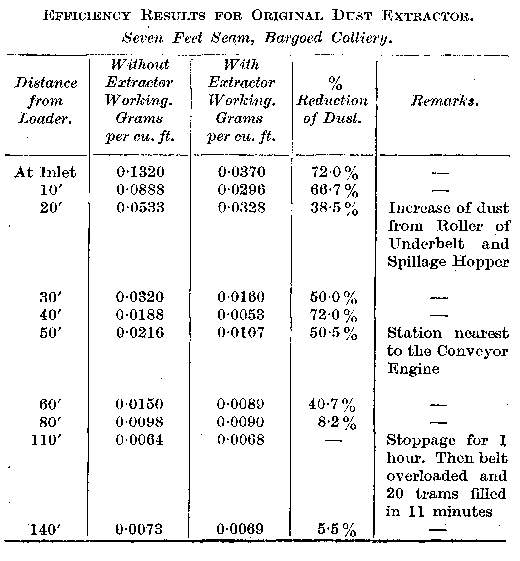
From sampling tests it was possible to determine the actual efficiency of the dust extractor. The amount of dust present in the air between the conveyor loader and the coal face for the two cases are tabulated in the table herewith, together with the percentage reduction of dust at various distances from the loader.
The position of the loader, or zero mark, from which all measurements were made during the tests, was the edge of the loading chute.
 |
 |
| Names mentioned in this article | |
 |
 |
| Name | Age | Occupation | Notes |
|---|---|---|---|
| Griffiths, J. Howard | Investigator | ||
| Jones, T. David, Dr. | Professor of Mining | ||
| Terrell, W. A. | Investigator |
|
|
| Links to Collieries/Mines mentioned in this article | |
|
|
 | Bargoed Colliery |
 |
 |
| Related Articles | |
|
|
| Pub. Date | Article (Newspaper) |
|---|---|
| 27 Jul 1940 | Loading-Point Dust, South Wales Committee's Report (The Science and Art of Mining) |
| 10 Aug 1940 | Loading-Point Dust, South Wales Committee's Report (The Science and Art of Mining) |
| 19 Oct 1940 | Spray And Mist Projector Tests, Investigation in South Wales Coalfield (The Science and Art of Mining) |



 Contains public sector information licensed under the

