


| Newspaper Articles |

|
Newspaper Articles |
 |
 |
9th March 1929, Page: 260, Column: 1
Roof Control In A Machine-Worked Mine
By Alan Hill.
From paper read before the Past and Present Mining Students' Association in the Wigan Mining and Technical College. Mr. Hill is Manager of the Parsonage Pits at West Leigh, Lancashire.
Strata Movement.
Undisturbed strata are under the influence of two potential forces. The first due to gravity acts vertically downwards and may be taken as roughly 1 lb. per square inch per foot of depth, therefore for a seam, lying at a depth of 1,000 yards, this pressure would amount to 3,000 lb. per square inch. The second force consists of compressive stresses induced in the earth's crust due to its cooling and consequent contraction. This force is generally considered to act in a more or less horizontal direction, and that it must be of enormous magnitude is evident from the many geological features that we so often have to consider. So long as the strata remain undisturbed these forces remain in equilibrium, but when excavation is commenced in a seam the forces are liberated, and their joint action is responsible for all the phenomena of subsidence.
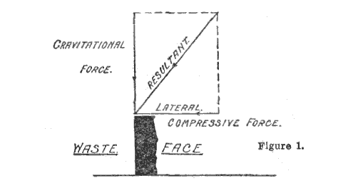
A moment's consideration of the weight of the overlying strata, and the strength of the supports used in a roadway, will show that the lateral compressive forces must help to hold up the roof and re-act considerably on the gravitational force. The lateral force will act away from the undisturbed area towards the disturbed portion, i.e., in the opposite direction to that of the advance of the face or towards the waste. The joint action of the two forces is thus the resultant of a vertical and horizontal component which acts in a slanting direction downwards and towards the waste. (See Figure 1.)
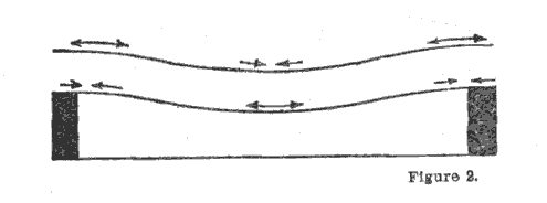
Before dealing with the conditions obtaining on a longwall face, we might consider the roof action in a narrow heading such as would be driven to open out a longwall face, and then trace the various stages of this action as the area of excavation increases. It is also permissible to consider the strata immediately overlying the seam as a series of beams, the greater portion of whose weight is borne by the coal pillars at either side of the heading.
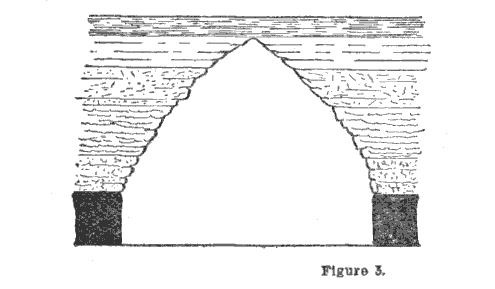
Referring to Figure 2, it will be seen that the stresses set up in the lowest beam as a result of the kinetic, gravitational and lateral compressive forces vary between the upper and lower surfaces of the beam, and also along the unsupported length of each surface. Thus, the lower surface is in compression at each end, and in tension at the centre, while the upper surface is under compression at the centre and in tension at the ends. In addition, there is a shearing force which has its maximum value at the ends and diminishes to nothing at the centre. As a result of these stresses the beam may break in one of two ways, depending on its resistance to compression, tension and shear ; as a rule it fails at the centre, but it can and sometimes does fail by shearing at one end. In either case the various stresses are now imparted to the second beam, which is strained in exactly the same way, except that it has a shorter span. As this fails the next beam in turn is subjected to stress, and so the action goes on until a natural arch is formed (Figure 3) above which we have other members which are in equilibrium and may be expected to remain so until disturbed by further excavation.
In the case of a roadway the object of timbering is to prevent the fall of small pieces of stone, and in particular what may be termed the keystone of the arch, the displacement of which would upset the equilibrium of the arch and set up further stresses.
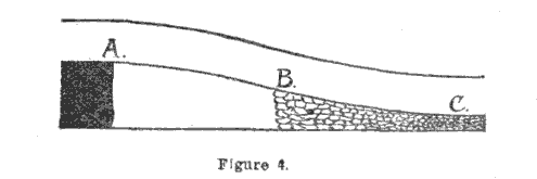
Coming now to the consideration of the effect on the roof of further excavation, if we assume that at first the roof does not break, it will gradually bend until it assumes a position such as that shown in Figure 4. As in the previous case the joint effect of the gravitational and lateral forces is imposed on the roof at the edge of the coal, with the result that planes of weakness and often actual fractures are produced which incline over towards the goaf. From "A" to "B" the bend of the roof is concave and is under compression, so that no further strain is imposed on the planes of weakness, or in the case of actual fractures, the curvature of the roof tends to lock the individual pieces and keep them in place. From "B" to "C" the curvature becomes convex, and the consequent tensile stress produces breaks in the planes of weakness, and the opening out of the breaks allows pieces to drop out, which immediately relieves the strain on the roof by decreasing the shear stress at "A." One immediate consequence of this is that a general re-arrangement of stresses takes place in the roof, and is generally accompanied by a serious disturbance known as a crump. In order to explain the further results it is necessary to employ once more the beam analogy.
The broken roof is now analogous to a cantilever, the lower surface of which is in compression, and the upper in tension. Somewhere between the two surfaces there will be a plane in which neither tensile nor compressive stresses exist, this is called the neutral plane. The exact position of the plane will depend on the ratio of compressive to tensile strength of the material. If these are equal, the neutral plane will be midway between the two surfaces, but rocks are stronger in compression than in tension, and the average figures for sandstone are:—
| Tensile strength in tons per square inch | 0.41. |
| Compressive | 3.51. |
Thus it can be said that sandstone is something like nine times as strong in compression as in tension, so that the neutral axis will be roughly one-ninth depth above the seam or eight-ninths depth below the surface. It is not sufficient to only consider the nature of the forces, but also changes in their relative magnitude. Both forces are at a minimum at the neutral axis, and the compressive forces increase downwards until they are at a maximum at the seam, whilst the tensile stresses increase upwards from the neutral axis to the surface. In practice, however, it is found that the main breaks immediately above the coal are thrown back over the goaf and extend as far as the neutral axis. Above the neutral axis, due to the stress changing from compression to tensile, the magnitudes of these tensile stresses are also increased as we proceed upwards, and the breaks are thus thrown over the coal face in a forward direction.
Applying these theories to the mass of strata overlying a coal seam, the predominating factors which influence the extent to which the lines of fracture penetrate the main roof, and their probable results, are :—
(1) The amount of subsidence of the nether roof, which depends on the thickness of the seam and method of working.
(2) Direction of cleavage in relation to direction of working.
(3) The depth of the seam from the surface.
(4) The presence or absence of overlying strata strong enough to bridge the unsupported span.
(5) Presence of faults or other planes of weakness due to folding or thrust planes.
 |
 |
| Names mentioned in this article | |
 |
 |
| Name | Age | Occupation | Notes |
|---|---|---|---|
| Hill, Alan | Colliery Manager | Whos Who Page |
 |
 |
| Related Articles | |
|
|
| Pub. Date | Article (Newspaper) |
|---|---|
| 09 Mar 1929 | Roof Control In A Machine-Worked Mine (The Science and Art of Mining) |
| 23 Mar 1929 | Roof Control In A Machine Worked Mine (The Science and Art of Mining) |
| 06 Apr 1929 | Roof Control In A Machine-Worked Mine (The Science and Art of Mining) |



 Contains public sector information licensed under the

