


 |

|

|

|
|
 |
 |
|||
The Installation and Moving Over of a Face Belt Conveyor
Training Manual No. 1Chapter II
MAKING A JOINT
 First cut the belt ends square as described in section A below, and then fix whichever type of fastener is to be used, as described in Section B.
A SQUARING THE BELT ENDS
Tools and materials required :-
Sharp knife
Piece of chalk
Set square
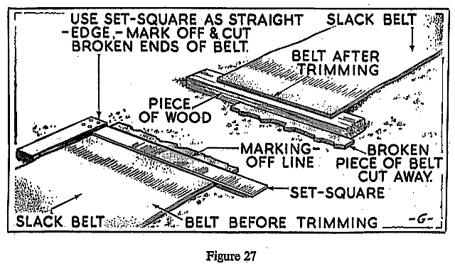
Using the set square, mark off the ends of the belt and then cut (Figure 27). It is most important that the cut should be square with the sides of the belt.
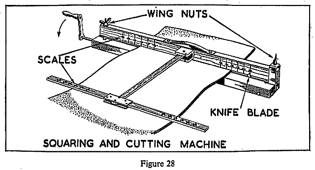
Small portable machines can be obtained for the purpose of cutting the belt square. One of these types is shown in Figure 28.
Note: If the belt edge is not true enough for the set square, chalk a centre line down the belt based on four or five cross measurements at intervals of six or seven feet.
B APPLYING THE FASTENERS
(i) Plate or hinge type
Tools and Materials required :-
Soft wood sleeper
Short piece of H Section Girder or Riveting Fixture
Hand Hammer (about 1 lb. weight)
Crow bar
Set of Couplings (either the long type to cover the whole width of the belt or the small type, whichever is used)
Coupling Pin
Rivet holder
Copper or Steel Rivets
Knocking out pin or drifter
Hollow draw punch
Where the Girder is used :-
1. Place the squared belt end between the plates of the coupling.
2. Insert the knocking-out pin or drifter into the pin slot of the coupling and press the belt against it making sure that the coupling is square with the edge of the belt and that the knocking-out pin is free enough to move (Figure 29).
3. Place on soft wood bar which has been set firmly so that it will not rock.
4. Insert a rivet, held in holder, into the end hole of the coupling (Figure 29).
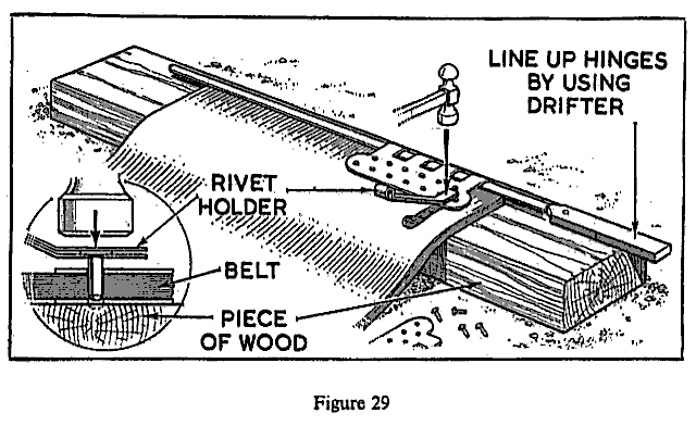
5. Using a hand hammer, hammer the rivet through the belt and the hole in the other plate of the coupling [Figure 29 (inset)].
6. Repeat (5), hammering the rivet through the hole at the opposite end of the coupling. This is to keep the coupling fixed square to the belt edge.
Repeat for the remainder of the holes in the coupling.
7. Remove soft wood sleeper and replace it by the short piece of steel girder.
8. Turn over the belt and place the coupling on the girder [Figure 30(b)].
9. Place a washer over the end of the rivet and then with a hollow draw punch drive the washer tightly on to the coupling [Figure 30(a)].
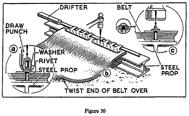
10. Hammer over the end of the rivet, making a firm joint [Figure 30(c)].
11. Repeat 9 and 10 to rivet the remainder of the holes.
12. Remove the drifter.
13. Repeat operations 1 to 12 on the other belt edge which has to be joined, making sure the coupling used mates with the one just fixed.
14. Place the lengths of the belt so that the couplings mate properly and insert the coupling pin (and cotters where they are used) (Figure 31).
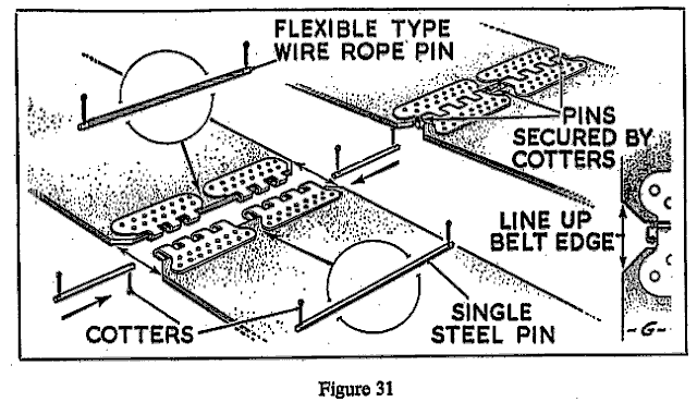
15. Cut ¾ inch off each corner of the belt (Figure 31).
Where a Riveting fixture is used :-
(1) Place a set of half couplings in the fixture and hold them in position by inserting the coupling pin (Figure 32).
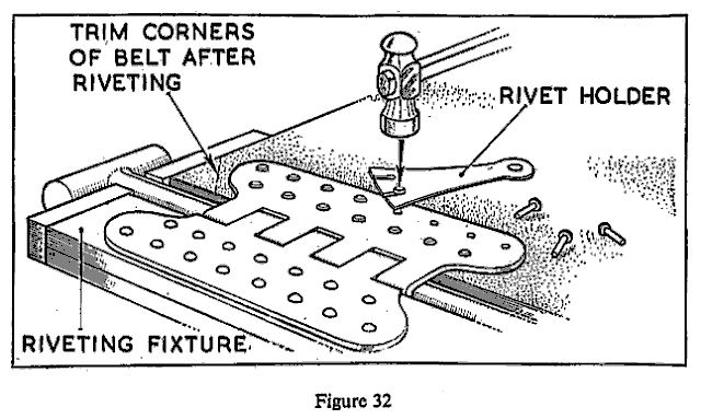
(2) Insert the squared belt end into the set of half couplings.
(3) Drive the rivets through the couplings and the belt.
(4) Remove the pin and turn the belt over.
(5) Draw the rivets through by using the hollow draw punch. Place washers over the ends of the rivets, With the punch, drive the washers tightly on to the coupling.
(6) Hammer down the heads of the rivets.
(7) Repeat 1 to 6 on the other set of half couplings.
(8) Place the couplings together and insert coupling pin (and cotters where they are used).
(9) Trim the belt corners ¾ inch.
Note: If the work has been done properly, the lengths of belt will be correctly aligned.
(ii) Bristol Couplings
Materials and tools required :-
Soft wood sleeper
Hand hammer
Hammer (about 2 lb. weight)
Crow bar
A Set of Bristol couplings
1. Set the soft wood sleeper in a firm position so that it will not rock about.
2. Place the two trimmed belt ends together on the wood sleeper. Align the two lengths of the belt correctly so that the edges are not staggered (Figure 33).
3. Holding the belt ends together, place a Bristol coupling about ¾ inch from one edge, positioned equally over each belt end (Figure 33). Hammer the claws of the coupling through the belting with the 2-lb. hammer.
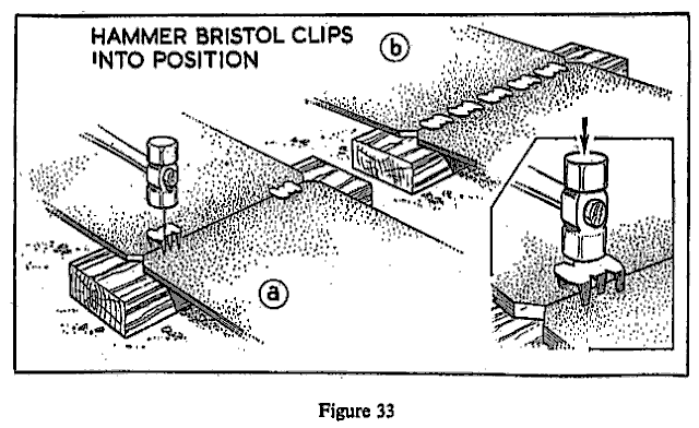
4. Holding the belt firmly in position, hammer a coupling into the other edge of the belt about ¾ inch from the edge.
5. Place a coupling in the centre of the belt joint and hammer home.
6. Repeat the operation until the whole of the joint is covered by the couplings (Figure 33).
7. Raise the joint from the sleeper — use the crow bar as the claws will have pierced the sleeper.
8. Turn the belt over, placing the joint back on the sleeper.
9. With hand hammer turn over the claws towards the coupling. Hammer them flat to prevent them catching on the conveyor structure when the belt is running (Figure 34).
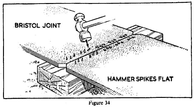
10. Trim the belt corners ¾ inch.
(iii) Hayden Nilos Coupling
Materials required :-
Hayden Nilos belt fastening machine
Box of fasteners
Coupling pin
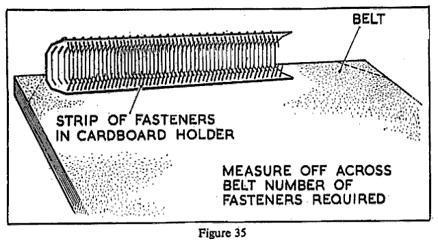
1. Measure enough cards of fasteners for the full width of the belt except for 1 inch on either side (Figure 35).
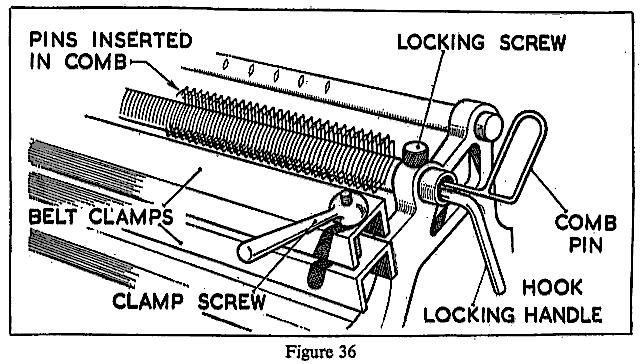
2. Remove the comb pin (Figure 36).
3. Release the locking screw of the comb on the machine and turn the comb so that it is facing upwards.
4. Insert cards of fasteners into the comb with hook locking handle away from operator. Replace the comb pin, so holding each of the fasteners in position (Figure 36).
5. Turn comb and fasteners to face the belt clamping device and tighten the comb locking screw. Then turn the hook locking handle upwards locking the fastener against the spindle (Figure 37).
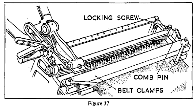
6. Thread the trimmed belt end through the clamping device between the hooks of the fasteners until it fits tightly against the comb (Figure 37).
7. Screw the handles of the clamping device down to fasten the belt in position.
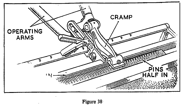
8. Pass the jaws of the cramping device over a set of fasteners at one edge of the belt. Pull the handles of the cramp together to force the fasteners into the belt.
9. In the same way fix all the fasteners into the belt.
10. Return the cramping device.
11. Pass the clamp over the fasteners again, giving them all a final clench (Figure 38).
Note: The tube handle with ring attachment should be placed on the top jaw. The ring prevents the foot from slipping when giving the final clench.
12. Slacken off the comb locking screw and remove the comb pin. Slacken off the belt clamping screws, turn the comb upright thus releasing the belt.
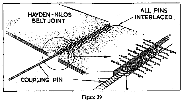
13. Remove the belt from the machine and trim the corners ¾ inch at either edge (Figure 39).
14. Repeat 5 to 13, using the other prepared belt end.
15. Place both ends together, interlacing the fasteners, and insert a coupling pin (Figure 39).
(iv) Comet Lacing
Materials required:-
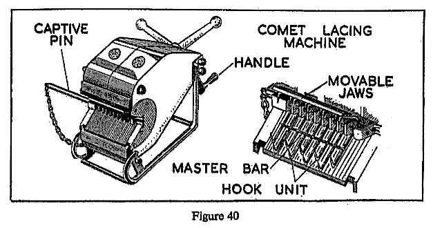
The Comet Lacing Machine (Figure 40).
Tin of fasteners
Flexible Coupling pin
1. Take sufficient fasteners to cover the full width of the belt except for 1 inch on either side.
2. Open the jaws of the lacing machine by turning the handle in an anti-clockwise direction.
3. Draw out the captive pin.
4. Insert one of the hook units into the milled slots of the comb with the masterbar downwards (Figure 40).
5. Insert the captive pin to lock the hook units in position.
6. Insert the prepared belt end between the teeth of the fasteners, about 1 inch from one edge, so that the belt fits tightly against the comb, the captive pin on the side away from the belt edge.
7. Close the jaws of the machine by turning the handle in a clockwise direction thus forcing the fasteners into the belt giving them a final clench by turning the handle until the jaws will close no further.
8. Repeat operations 2 to 5.
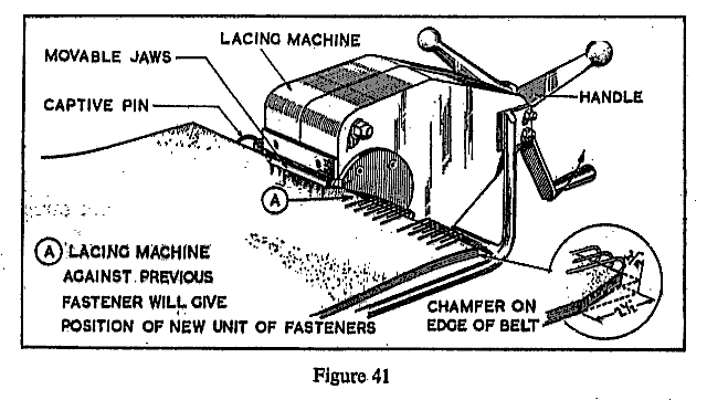
9. Move the machine along the belt until the end of the comb (away from the end into which the captive pin is inserted) rests against the last hook of the unit previously inserted (Figure 41).
10. Repeat operations 6 and 7 to fasten the hooks in position.
11. Repeat all the above operations until fasteners have been inserted into the whole width of the belt except for 1 inch at either edge.
12. Attach fasteners on the other prepared belt end.
13. Place both ends together, interlacing the fasteners, and insert flexible coupling pin.
14. Trim the corners of the belt at the joints.





 Contains public sector information licensed under the

