


 |

|

|

|
|
 |
 |
|||
The Installation and Moving Over of a Face Belt Conveyor
Training Manual No. 1Chapter II
INSTALLING A FACE BELT CONVEYOR
 1. Make sure that the track for the conveyor is clear of debris and reset supports that are not in line so that the conveyor can be laid perfectly straight.
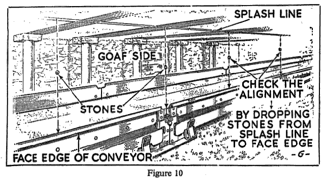
2. Align three flame lamps (Figure 5) at convenient distances along the face. Join them by a string held to the roof and whitewash a line on the roof using the string as a guide. This splash line is to be used to check the straightness of the conveyor.
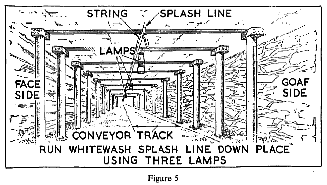
Note: We shall assume that this line should be directly over the edge of the conveyor. At some collieries the props are set to a line and the conveyor is erected at a specified distance from them.
At other collieries a length of piano wire is stretched along the face at spill plate level and the conveyor is aligned to it.
3. Place the engine end in position, face edge in line with the line on the roof (Figure 6). It should be so placed that the coal will be delivered properly either into the tub or the gate conveyor, whichever is used.
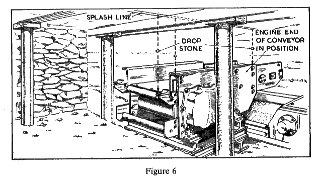
Where the floor is taken up it may be necessary to build the engine end up on skids equal in height to the depth of dint (Figure 6).
Note: As a precaution against fire, avoid the use of wood when building up the engine end.
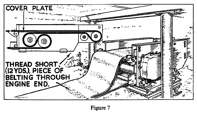
4. Remove the cover plate of the drivehead and thread a short piece of belting, approximately 12 yards in length, from the bottom of the drivehead round the driving drum(s) (Figure 7 inset). Replace the cover plate and then pass the belt back over the cover plate on top of the drivehead (Figure 7).
Note: (a) Use a length of soft iron wire to facilitate the threading of the belt.
(b) Do not switch on the power when threading the belt.
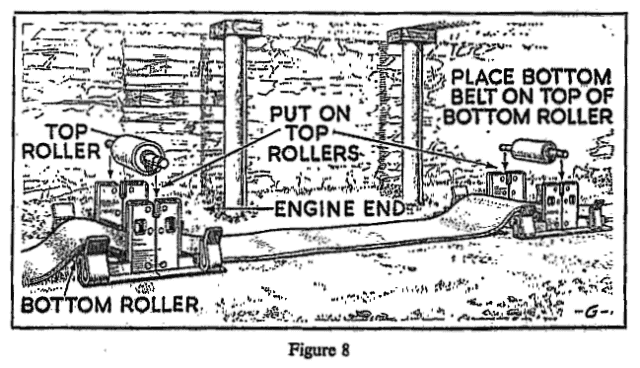
5. Roll out and connect lengths of belting along the floor of the conveyor track to form the bottom belt. (For Belt Jointing see Part II.)
6. Lay Stools or Standards under this belt at distances apart equal to the lengths of the intermediate sections (Figure 8). Some stools, such as those shown, must be placed so that the bottom rollers are towards the engine end. Insert top rollers.
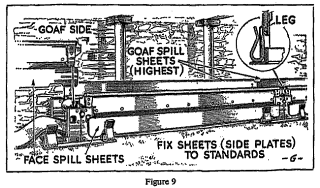
7. Complete the building of the intermediate sections by fixing the Spill Plates firmly to the stools (Figure 9). The higher spill plates should be placed on the goaf side.
8. Roll out and connect lengths of belting on top of the intermediate structure to form the top belt, making sure that it lies centrally in the structure.
9. Check and adjust the alignment of the conveyor. This is best done by suspending a plumb bob from the line on the roof, but the more rough and ready method of dropping a stone from the line is usually practised (Figure 10).
10. Place the tension end in position with the face edge under the line on the roof, leaving sufficient room beyond it for tensioning the belt.
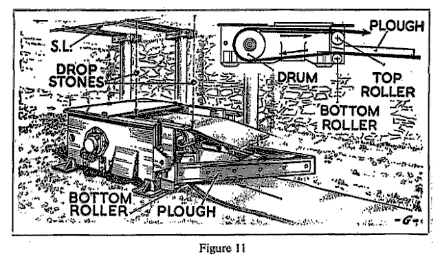
11. Thread a short length of belting (approximately 12 yards) round the return drum so that it passes over the bottom roller and under the plough (Figure 11).
12. Connect the bottom part of this piece to the bottom belt laid out on the floor.
13. Place the telescopic section, where one is used, in position.
14. Connect the top belt to the short piece round the tension end (otherwise leave the tension end uncoupled until the belt has been tensioned).
15. Stay the engine down by placing stays from the engine to the roof (Figure 12).
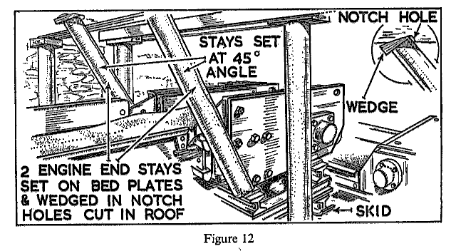
Note: Do not place the stays on the motor or on top of the gearbox, as the motor and gears may be strained and damaged.
16. Fix the Sylvesters to the Anchor Props at the tension end. (Figure 13).
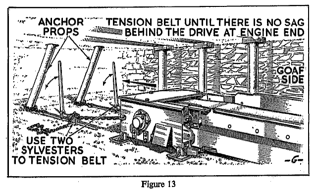
17. Tighten the belt by pulling the tension end back.
18. Attach the flexible cable (or air hose) to the motor after ensuring that it is clean and dry.
With electric machines see that the isolator switch on the gate end box and the motor switch are in the "off" position before the cable plugs are inserted into the sockets.
19. Check that the belt runs properly on the driving and tension drums and that it remains central and rides on all the intermediate rollers. To do this proceed as follows.
| (a) |
Place men within hearing distances of each other at the engine end, tension end, and at suitable intermediate positions so that they can pass instructions to one another.
| |
| (b) |
Switch on the power.
| |
| (c) |
While the belt is running apply more tension to the belt at the tension end until there is no sag behind the drive at the engine end. If the belt runs to one side on the return drum, pull on the sylvester at the same side. This will make the belt run centrally.
| |
| (d) |
Centralize the belt on the driving drum by aligning the drive head afresh and resetting the stay props. During these adjustments the belt must be stopped ; otherwise the engine might spin round.
| |
| (e) |
Check with the belt running that it runs centrally along its whole length. Also that it rides on all the rollers when running empty. Where it does not, the stools should be packed up from the floor.
| |
| (f) |
All stools or standards should be set so that they do not rock.
| |
| (g) |
All rollers should rotate freely. Those that do not should be replaced.
|
IMPORTANT POINTS
Before a conveyor will work properly and efficiently five important conditions must be satisfied.
| (a) |
The whole conveyor, engine, intermediate sections and tension end must be in a straight line. This is of the utmost importance.
| |
| (b) |
Each section of the Conveyor must be set firmly so that it does not rock about or get out of alignment.
| |
| (c) |
The Engine End and Tension Ends must be securely anchored.
| |
| (d) |
The belt must be tight enough to prevent it from slipping on the driving rollers, but not so tight that it is under undue stress.
|
Unless the conveyor is always erected with the greatest care, an excessive amount of belt wear will be caused. It is essential that the longest service should be obtained from the belt.
| (e) |
The machinery must be kept properly oiled and greased. The correct grade of oil must be used for the motor and gearing. Coal must be prevented from entering the gearing as it will clog the gears and there will be excessive wear of the teeth. Inspection covers must therefore be kept properly in position.
|





 Contains public sector information licensed under the

