


 |

|

|

| |
 |
 |
|||
November, 1956
The Sandwith Anhydrite Mine — Part 2
Drawings and Photographs accompanying the article
| Sample | Description |
|---|---|
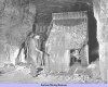 | Fig. 10. A Muir-Hill 4½ cu. yd. hydraulic dumper discharging its load at the grizzley over the hopper |
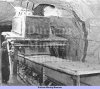 | Fig. 11. The loading point underground where anhydrite is transferred to the conveyor belt for transport to surface |
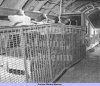 | Fig. 12. One of the transfer points on the Sutcliffe 36 in. conveyor |
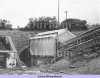 | Fig. 13. Portal of the north drift showing the conveyor belt installation |
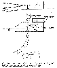 | Fig. 14. Plan and elevation drawings showing the surface arrangement of the fresh air fan |
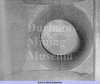 | Fig. 15. View inside the fan duct of the 90 in. Sirocco turbo-axial fan |
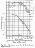 | Fig. 16. Performance curves for the 90 in. Sirocco turbo-axial fan |
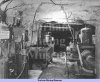 | Fig. 17. The mine’s requirements of compressed air are supplied from an underground installation of six Ingersoll-Rand compressors |
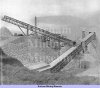 | Fig. 18. The surface stockpile of 3 in.-6 in. anhydrite, also showing the R.O.M. conveyor, belt weighing installation and primary crushing house |
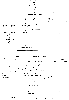 | Fig. 19. Flowsheet depicting the initial crushing and screening treatment for the anhydrite |
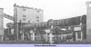 | Fig. 20. View showing one of the 230 ft. long Edgar Allen rotary kilns into which is fed the ground anhydrite, shale and coke mixture. From one end a gas containing SO2 is taken off for the sulphuric acid plant while the lime clinker from the other end is made into cement |
Article reproduced from a copy of the magazine held at National Mining Museum Scotland, Newtongrange, Midlothian.




 Contains public sector information licensed under the

