


 |

|

|

| |
 |
 |
|||
October, 1954
Electric rotary drilling in anhydrite
Drawings and Photographs accompanying the article
| Sample | Description |
|---|---|
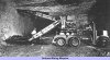 | The pneumatic-tyred electric rotary-drill carriage |
 | Fig. 1. — General arrangement of the drill carriage showing operating limits |
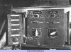 | Fig. 2. — The complete set of controls for positioning and operating the drills. The push-button panel seen on the left is carried by the driller when positioning either drill, while the separate controls for each drill are permanently mounted on the rear of the vehicle chassis and may be noted on the right of the illustration |
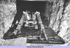 | Fig. 3. — The drills shown in position for starting off two opposing cross-cuts from a level |
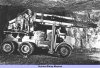 | Fig. 4. — The drilling equipment shown folded in the forward position ready for moving the carriage. The weight of the drill mounting is taken on a structure attached to the vehicle chassis |
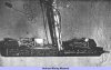 | Fig. 5. — Close-up view of one of the drill mountings while, in the left upper corner may be noted the operator's drill-positioning portable control panel |
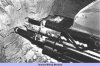 | Fig. 6. — View of the drill front end guide, showing the "feeler rams" for pre-loading the jib |
 | Fig. 7. — The illstration above depicts the front end arrangement of the drill showing the front end guide and clutch motor, while on the opposite page the rear end arrangement of the drill may be seen with the travelling head gearbox (upper diagram) and the 5 h.p. driving motor (lower diagram). To correlate the section shown on the left, see the upper diagram oposite |
 | Fig. 7. — The illstration above depicts the front end arrangement of the drill showing the front end guide and clutch motor, while on the opposite page the rear end arrangement of the drill may be seen with the travelling head gearbox (upper diagram) and the 5 h.p. driving motor (lower diagram). To correlate the section shown on the left, see the upper diagram oposite |
Article reproduced from a copy of the magazine held at National Mining Museum Scotland, Newtongrange, Midlothian.




 Contains public sector information licensed under the

