


 |

|

|

|
|
 |
 |
|||
April, 1954
Beckermet Mine — Part 1
At the West Cumberland hematite mines, operated by the Beckermet Mining Co. Ltd., a subsiduary of the United Steel Companies Limited, modern equipment is being installed to reduce mining costs, and development is proceeding to proved orebodies.
Near Egremont, five miles south-east of Whitehaven, Cumberland, England, are located the properties of the Beckermet Mining Co. Ltd., who are one of the two remaining mining companies operating on the concealed orefield in this particular locality, while some three companies are left in the Cumberland and Furness orefield as a whole.
The hematite industry in West Cumberland was at its height of productivity during the latter part of the last century, and a total annual output of some two million tons of ore was reported.* Since the end of the first world war a gradual decline in output has occurred due to the exhaustion of mines working the exposed orefields, and production has come mainly from the concealed ores in the area south of Egremont. Comparative annual tonnage figures may be quoted as 1½ million tons in 1917, and approximately 675,000 tons in 1938 however, in 1946, total hematite production from the area amounted to less than 400,000 tons.
The Beckermet Mining Co. Ltd. was formed in 1903 after preliminary surface drilling had shown some hematite ore. No. 1 shaft was sunk to 1,164 ft. after the formation of the company and production started in 1906. This vertical shaft was deepened to its present level of 1,374 ft. between 1912 and 1915. Sinking on No. 2 shaft, also vertical, was commenced in 1916, and after bottoming at a depth of 1,247 ft. production was obtained through it in 1918.
These two shafts were used to develop and exploit the Winscales-Mildred deposit, and underground exploration revealed this orebody, which may be noted from a reference to the illustration on page 154, to be an extension to the south-east of that worked by the Florence and adjacent mines. This entire deposit has since proved to be one of the largest ever found in Cumberland.
The Beckermet mines were taken over by the United Steel Companies Limited in 1920 together with some twelve other hematite producers in the Cumberland orefield. At one time prior to the nationalisation of the coal industry, these companies were virtually self-contained, operating or controlling producing properties working the essential raw materials for the manufacture of steel by the acid Bessemer process. Nowadays, however, coal has to be obtained from the N.C.B. while 75 per cent, of the iron ore required at Workington comes from North Africa, Spain and Sweden. The firm still maintains its own limestone quarries and fireclay mines, the latter supplying the material for the furnace firebricks.
Peak production from the two Beckermet shafts was reached in 1929 when an annual output of 307,000 tons of hematite was hoisted. Relatively recently, fresh deposits were located east of Haile village, and as a result the Haile Moor shaft was sunk in 1939, coming into production in 1942. With a total (all shafts) production in 1952 of 125,000 tons, the company has carried out an intensive surface boring programme, and underground development is being extended to the most promising areas as indicated by the correlation of these borehole results. To help in the work of relating the borehole findings and limestone faults to the hematite bodies, the excellent model, shown in Fig. 3 with the cover glass removed, was constructed and is now housed in the surface buildings at the Haile Moor shaft. The position of the three shafts may be noted from the flags, while the vertical sticks represent the numerous exploratory boreholes put down from the surface; the camera view of the model is approximately north-east in this photograph.
Most of the exploration drilling is done by Henry Bowes & Son, boring contractors, of Egremont, who have been undertaking this work for the company since 1933. Hole depths range from 500 to about 2,000 ft., and diesel-driven rigs are used for the shorter holes up to 1,200 ft. in depth, and of 5 or 6 in. diameter. Deeper holes, put down by steam rigs using 50 ft. derricks, usually commence with a 10 in. diameter core tube. At present all drilling is done using the chilled-steel-shot method, although both tricone bits and diamonds have been tried in the past, but were discarded from loss-of-circulation troubles or high diamond costs when drilling in the sandstone respectively. The method currently used gives excellent recovery of cores.
Geology
The hematite occurring in the West Cumberland orefields, the disposition and extent of which may be seen in the geological map shown in Fig. 1, may be said, for all practical purposes, to be confined to the Carboniferous limestone series ; in the last twenty years, all the ore extracted from this producing locality has been taken from this rock series. A reference has been made previously to the exposed orefields lying to the north-east of Egremont, and in these instances this limestone series is exposed at the surface. However, in the area south-east of Egremont in which is located the operations of the Beckermet Mining Co. Ltd., the carboniferous limestones are overlain, and hence concealed, by a series of unconformable cover rocks of Permo-Triassic age. These series are set out in tabular illustrated form in Fig. 2, shown on the page facing. From this, it may be observed that these cover rocks, varying in thickness up to 1,850 ft. or more, comprise generally the St. Bees sandstones and shales lying on top of magnesian limestone and brockram (or breccia). The superficial deposits formed in modern times on top of the cover rocks comprise river gravels and alluvium, and it is within these glacial gravels together with the upper part of the sandstones that the main ground water horizon is located. Within the Beckermet mining area the limestone rocks rest on the Borrowdale volcanic ash, but in the case of the neighbouring properties of Florence and Ullcoats, the floor is composed of Skiddaw slates.
Two phases of earth movement, Pre-Trias and Post-Trias, caused the existing folding and faulting of the limestone rocks; after this came the partial erosion of this series, followed by the deposition of the cover rocks. Although many theories have been advanced over the origin of the hematite deposits, it is generally agreed that the ore must have been formed by the metasomatic replacement of the limestone by the action of iron-bearing solutions. A typical cross-section is shown in Fig. 5 from which it will be seen that the ore deposits, both in vein and flat form, occur near the faulted areas; the indications are that the solutions have percolated along the fault planes intersecting the limestone, and have spread outwards along the bedding planes, thus attacking the limestone and changing it into hematite accompanied by the associated gangue minerals comprising quartz and barytes.
Relating to the origin of the orebearing solutions and their movement, four theories have been advanced. However, the one supported by the staff of the mining company accepts the principle that the solution entered at or near the outcrop of the limestones and migrated generally down dip, principally through the shattered rocks immediately adjacent to the faults. A complete seal is provided by the breccia over much of the area, but it has been broken by one or more major faults. Ironbearing solutions entering the limestone at or near the outcrop of the volcanic ashes or slates developed a hydraulic head sufficient to force them through the limestone shatter zones and thence into the sandstone.
This theory is supported by the geological evidence available, which indicates that the breccia provides an impervious seal between the water-laden St. Bees sandstones and the dry limestone beds. This was confirmed by the opinions of some of the members of the XVIII International Geological Congress who visited the Haile Moor operations in 1948. It follows naturally that the problem of determining the factors governing the deposition of the hematite governs to a large extent the decisions of the management relating to the surface drilling and exploration programme being pursued in the search for new orebodies.
A mineralogical description of the average ore being mined and shipped to the furnaces may he given as:
| Hematite | 49.7 | per | cent. |
| Limonite Fe2O3.H2O | 20* | " | " |
| Quartz SiO2 | 8.5 | " | " |
| Clay (hydrated aluminium silicate) | 4.7* | " | " |
| Calcite CaCo3 | 2.4 | " | " |
| Dolomite CaCo3.MgCO3 | 1.8 | " | " |
| Barytes BaSO4 | 5.0 | " | " |
| Pyrites FeS2 | 0.4 | " | " |
| * The figures for limonite and clay can only be approximate due to the difficulty in distinguishing between moisture and combined water. | |||
Shafts
It has been mentioned previously that the company operates three shafts, the locations of which in relation to one another and to the orebodies worked may be noted from Fig. 7.
No. 1 shaft was originally put down as a three compartment rectangular type measuring 17 ft. 6 in. by 7 ft. 9 in. and containing two winding compartments; the third compartment housed the rods of a Cornish beam pump. However, in 1945 an unfortunate disaster occurred when part of the rod column of the Cornish pump broke away bringing down much of the shaft timbering, and necessitating a great deal of work in the reclaiming of the shaft. It was therefore decided to convert No. 1 shaft to an elliptical shape and work started on this in 1946; internal size is now 21 ft. on the long dimension and 11 ft. on the short axis. It is lined throughout with precast concrete blocks apart from a 28 ft. brick-lined collar. Single-deck cages are employed, riding between centred guides of 90 lb. steel rail, supported on steel buntons. Also carried in this shaft is an 8 in. air column, two rising mains of 10 in. and 8 in. diameter respectively, and two shaft feeders of 0.2 cable (carrying 3,300 volts to underground). The whole of this reconstruction was carried out by the company's own personnel. The present headframe, 66 ft. high with two 12 ft. diameter winding sheaves was installed in 1950 and manufactured by Head, Wrightson & Co. Ltd.
No. 2 shaft is rectangular, timber-lined measuring 21 ft. by 8 ft. 6 in. inside timbers and has two winding compartments, one man shaft, and one pump compartment. This shaft has not been used for hoisting ore since 1952, and at present is used for handling men and materials and as an upcast ventilation shaft. When the modern bath-house and changing facilities at No. 1 shaft (now in an advanced state of construction) are complete, No. 2 will be used only for ventilation purposes and as an emergency escapeway.
The Haile Moor shaft was sunk elliptical in shape to a depth of 800 ft. and, as with the No. 1 shaft reclamation work, was lined with precast concrete blocks below the 26 ft. brick-lined collar; the internal measurements are 21 ft. on the long axis and 12 ft. across the short dimension. A feature of particular interest in this shaft is a 6 in. partition wall, constructed of concrete, enabling the shaft to contain both upcast and downcast ventilation compartments. The downcast section houses the main winding compartments through which ore, rock, men and materials are handled in a normal manner. The upcast portion of the shaft area is equipped, however, for emergency handling, as a standby auxiliary hoist (capable of operation on either steam or compressed air) is located on surface. This section of the shaft is connected by means of a fan drift to a surface fan, which exhausts a volume of 25,000 cu. ft. of air per min. from the underground workings.
Mining methods
It will be appreciated from references both to Figs. 5 and 7 that no prevalent conformity exists as to the type, shape and size of the various hematite deposits worked. Mining methods, therefore, will naturally vary with individual orebodies, but generally a form of bord and pillar working is employed wherever practicable.
From the shaft, a main development heading is taken out to the bottom of the particular deposit, and continued throughout its length. At this elevation, the ore is blocked out with roadways driven at 40 ft. centres. Service raises, later used as storage and ore passes after the installation of timber chute drawpoints, are put up on or in the footwall and from these hoppers, as they are termed locally, sub-levels are taken off. These are sited at 25 ft. vertical intervals from sill to sill, continued upwards until the top of the hematite deposit is reached, as may be seen in Fig. 11. The sub-levels are then blocked out in a manner similar to that carried out on the bottom or main haulage horizon. The excavation performed in ore up to the completion of this phase of operations is naturally all termed stope development.
Following this comes the primary robbing of the pillars left between drifts; these are approximately 30 ft. square by 15 ft. high. The original headings, driven 9 ft. by 9 ft. or 10 ft. by 10 ft. are slashed by taking 3 to 4 ft. lifts from the side the full height of the drift. This work is carried in advance of the next operation of drilling and blasting down the back to a height that leaves a small floor pillar under the level above.
The remaining ore is now allowed to cave continuously and systematically, and the process of extraction of this caved hematite is termed secondary robbery. To obtain the necessary points for the hand loading of this ore, spiled drifts, 7 ft. by 7 ft. in cross-section and utilising Bathgate 3½ in. by 3½ in. TwinTrof girders for support, are driven through this caved ground to their extremities, so that all this ore is eventually won. Fig. 6 gives an indication of the type of ground encountered during this latter part of the mining process.
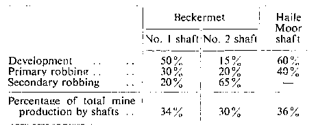
At the time of our visit to this mining property, the division of production from the three shaft areas and from the three mining stages was approximately as shown in the following table:-
Development
The standard size to which the majority of drift headings are driven throughout the mine is 9 ft. by 9 ft., and present practice is for a two or three man crew to drill, blast and muck out a 5 to 5½ ft. round (50-55 16 cu. ft. tubs) in one shift of eight hours; these men are also responsible for the installation of girder sets when ground is encountered that requires support. Roof bolting is employed in stratified ground, but in igneous rocks or broken-up ground, support of the workings is maintained by means of girder sets, corrugated sheeting and timber packing. Main development roadways to new deposits and those along which ore will eventually be handled by electric trolley locomotive haulage are driven to a cross-section of 11 ft. by 9 ft. Both wedge and burn cuts are employed, the choice being left to the discretion of the individual driller. In a 9 ft. by 9 ft. heading, 24 holes are normally drilled per round.
For drifting, drills mounted on pneumatic air-legs are now employed throughout the mines, having supplanted the drill jumbos on which two 3½ in. drifters were mounted. Three different machines are in use at the company's mines, the Holman SL-200 of the vented front head type mounted on a Holman air-leg, which may be seen in operation in a development heading in Fig. 8, the Atlas Diesel RH 754** mounted on the BMK pusher leg, and the Ingersoll Rand J40. However, it is understood from the mine management that future standardisation has been made on the former machine. Coromant 5 ft. 3 in. steels with tungsten carbide single chisel bit inserts, supplied by the Atlas Diesel Co. Ltd., are employed with the air-legs, although experiments are being made with other types. Drilling holes of 1 5/8 in. diameter, these 4¼ in. shanked steels average between 100 and 400 ft. per sharpening, depending on the prevailing ground conditions. Statistics have been kept on steel performance by the mine and, over a period of a year, an average of 119 steels was found to have given a footage of 1,376 ft. per steel.
For raising and stoping operations, standardisation is being made on the Holman Silver Bullet stoper. This drill has a bore and stroke of 2 5/8 in. by 2½ in., and weighs 95 lb. Raises are generally driven to 7 ft. by 11 ft. size, uncribbed and timbered into manway and materials compartments. Pikrose No. 1 tugger hoists are used for any necessary handling. Other drills in use underground comprise Ingersoll Rand J30 and J40 jackhammers, while prior to the introduction of the airlegs, all drifting was done with Climax SDV 3½ in. drifters.
Normal blasting throughout the mine is with "Blue sump" safety fuse and No. 6 detonators, while Gelamex No. 1 is the explosive used, These materials are all supplied by Explosives & Chemical Products Co. Ltd. Electric blasting is employed in raises or in wet working places. Explosive load is based on 3 to 4 lb. of explosive per cu. yd. of ground in situ, giving when broken either 2 tons of stone or 3 tons of ore.
Of special interest in connection with blasting operations is a mist projector, designed for the laying of dust. Made up at the mine, it consists of a standard Gardner Denver air-line oiler fitted with in. air and ½in. water pipe fittings. When the oiler is charged with a pint of castor compound, the device delivers a fine mist as the oil mixes with the water to reduce the surface tension, and this has been found most effective in wetting down dust particles.
The standard mine tub employed throughout the mine is a 16 cu. ft. steel bodied wagon manufactured by Robert Hudson Limited of Leeds. The axles are fitted with Timken roller bearings and the tubs have a loaded capacity of 20 cwt. of hematite ore; three of these loaded tubs go to make up one "pit ton," a term used throughout the company for production computation.
Face loading into tubs is performed mechanically wherever possible, while ore broken on the sub-levels is manually loaded into 11-cwt. bogies to the raise ore chutes. Mechanical loading on the levels is done with the aid of Eimco model 21 rocker shovels; Fig. 10 shows one of these loaders operating at the face of a heading being driven down at a grade of 1 in 4. This shovel embodies modifications made by the manufacturers to enable it to work satisfactorily on this dip, the salient difference between these and normal 21 loaders being that the rear axles of the dip machines act as wire-rope drums. Handling of tubs in this incline back to the California switch is by means of a 10 h.p. electric Pikrose No. 2 hoist, while above the switch, haulage is effected by a 50 h.p. Milburn electric single drum hoist. Trials have been carried out recently with the Eimco model 621 crawler mounted loader.*** Essentially this machine is a normal 21 above the turntable, carried on 8 in. wide tracks. Virtually on test at the time of visit, it was understood that the intention of the management is to utilise this machine in the primary pillar robbing stage of the mining process, thereby eliminating much of the present hand-filling in these areas.
* "Cumberland, A Survey of Industrial Facilities," published by the Cumberland Development Council Limited, and the West Cumberland Industrial Development Co. Ltd., 1951.
** "New Air-leg Combination," MINE & QUARRY ENGINEERING. vol. 20. No. 1, p. 42.
*** "Track-Mounted Rocker Shovel." MINE & QUARRY ENGINEERING, vol. 19, No. 12. p. 466.
Drawings and Photographs accompanying the article


Article reproduced from a copy of the magazine held at National Mining Museum Scotland, Newtongrange, Midlothian.




 Contains public sector information licensed under the

