


 |

|

|

| |
 |
 |
|||

February, 1954
The Billingham Mine - Part 3
Drawings and Photographs accompanying the article
| Sample | Description |
|---|---|
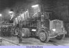 | Fig. 29 — An A.E.C. diesel truck shown preparing to tip its load at the undergound crusher station |
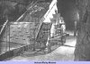 | Fig. 30 — This view at the crusher station dump illustrates the chute cover shown in the raised position |
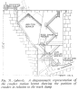 | Fig. 31 — A diagrammatic representation of the crusher station layout showing the position of cruser in relation to the truck dump |
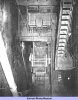 | Fig. 32 — Looking down into the crusher station. On the left may be seen the ventilation pipe for the removal of dust from below the crusher discharge |
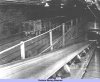 | Fig. 33 — In the left background may be seen a train in the Main West Level, while the belt in the foreground conveys -6in. material from the crusher |
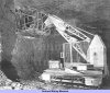 | Fig. 34 — A crew shown at work loading a face blast from a Jumbo crane platform |
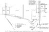 | Fig. 35 — Diagram illsutrating the panel ventilation system in the trackless mining areas |
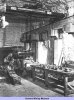 | Fig. 36 — In the underground workshops, part of which is shown herem excellent facilities for major maintence are provided |
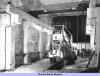 | Fig. 37 — This view of one of the maintenance bays shows travelling crane and strip-lighting employed |
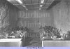 | Fig. 38 — Maintenance men enjoying their meal under ideal conditions in the underground canteen |
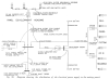 | Fig. 39 — Diagram showing the distribution of the electrical power supply to the mining panels |
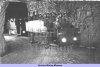 | Fig. 40 — Two Electicars shown transporting personnel to their working places at the start of a shift |
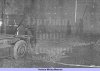 | Fig. 41 — The projector car shown in use at a face for making up the drilling pattern |
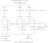 | Fig. 42 — Flowsheet for the milling operations |
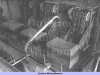 | Fig. 43 — A view inside the mill showing the three Ross chain feeders |
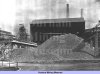 | Fig. 44 — The stockpile of +1 in. anhydrite. In the left background may be seen the head frame of No. 1 shaft |
Article reproduced from a copy of the magazine held at National Mining Museum Scotland, Newtongrange, Midlothian.




 Contains public sector information licensed under the

