


 |

|

|

| |
 |
 |
|||
January, 1954
The Billingham Mine - Part 2
Drawings and Photographs accompanying the article
| Sample | Description |
|---|---|
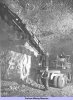 | Development of electric rotary drilling continues at Billingham with the Hardypick drill and I.C.I. turntable booms mounted on an A.E.C. chassis; one boom is shown swung forward as for travelling |
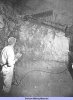 | Fig. 14 — The 5 h.p. Hardypick rotary drill showing the push-button control devised at the mine |
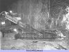 | Fig. 15 — In this view of the rotary drill, shown mounted here on the tracked chassis, the boom and drill mount assembly is well illustrated |
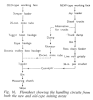 | Fig. 16 — Flowsheet showing the handling circuits from both the new and old-type mining areas |
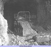 | Fig. 17 — Mechanical loading of the tubs in the old-type mining panels is handled by scraper-loaders |
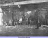 | Fig. 18 — View of one of the 150 h.p. rope haulages employed on the workings to the dip side of the Main West Level, which is seen in the foreground |
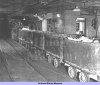 | Fig. 19 — Trolley locomotive and train of tubs seen in front of the weighbridge cabin, Main West Level |
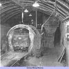 | Fig. 20 — The Nortons (Tividale) automatic tub tippler, showing in the right background the discharge chute fed by conveyor from the crusher station |
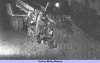 | Fig. 21 — Loading at the face in the new-type mining areas showing the gathering end of the Joy 18 H.R. loader |
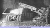 | Fig. 22 — The discharge end of the loader showing the boom, and the low, wide body of the truck |
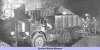 | Fig. 23 — The 150 h.p. A.E.C. diesel six-wheeled twin read-drive Mammonth chassis, mounting a special body taking a payload of 14 tons |
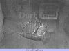 | Fig. 24 — International TD 14 tractor with Rsuston-Bucyrus bulldozer blade in use in the new mining areas |
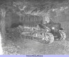 | Fig. 25 — Bulldozer cleaning up after a face blast |
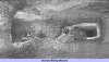 | Fig. 26 — Bulldozer, loader and diesel truck working in conjunction in the new-type mining areas |
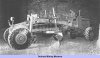 | Fig. 27 — Grader in use underground surfacing the main motor roads |
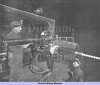 | Fig. 28 — Rotary drill shown mounted temporarily on a truck, when undergoing tests by the mine's research dept. |
Article reproduced from a copy of the magazine held at National Mining Museum Scotland, Newtongrange, Midlothian.




 Contains public sector information licensed under the

