


 |

|

|

|
|
 |
 |
|||

February, 1954
A new Washbox at Eppleton
The installation of a new type of Baum washbox at Eppleton colliery, No. 2 (Mid-East Durham) Area, Durham Division of the National Coal Board, has effected savings in non-productive manpower and increased the amount of high-grade coal available for marketing
Since Vesting Date the National Coal Board have installed over 107 coal-preparation plants. During the same period the amount of underground mechanisation has also increased, and as Table I shows, the increase in mechanisation has been, if anything, at a slightly higher rate than which coal-preparation facilities have been provided.
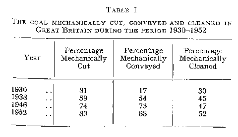
This factor, together with others, has led to the overloading of existing coal-preparation plants up and down the country. Happily, the National Coal Board's coal-preparation engineers are well aware of the implications of the situation and, together with the interested manufacturers, they are pursuing a vigorous policy designed to increase the prepared-coal throughput. At the same time much thought is being given to improving the design and performance of coal-cleaning equipment.
At Eppleton colliery in the No. 2 (Mid-East Durham) Area of the Durham Division, N.C.B., for instance, there is an installation which incorporates a new type of Baum-jig washbox, together with the necessary screening and allied units.
The complete arrangement has been installed within an existing building which contains hand picking tables, the washbox and ancillary plant, occupying the building space which was previously taken up by one picking table. A flowsheet of the washery is given in Fig. 1.
Before the installation of the washery the minus 2 in. size from the run-of-mine coal was cleaned in a dry-cleaning plant which has been in operation since 1936. All the material over 2 in. was hand picked while it passed over four plate-type picking tables — supplied by J. Joicey Limited of Newcastle-upon-Tyne. In accordance, therefore, with the policy of the National Coal Board to upgrade the available quantity of marketable coal and at the same time to release men for other productive duties, it was decided to install a washbox which would clean coal of ½ in. sq. to 3 in. rd. in size. However, the installation is only to cover an initial stage in a long-term development plan. As already stated, the washbox is of the Baum jig type, designed, manufactured and installed by the Automatic Coal Cleaning Co. Ltd. (Acco), of Carlisle, and cleans material of from ½ in. to 3 in. size, the minus ½ in material being treated in the dry-cleaning plant.
Raw-coal feed
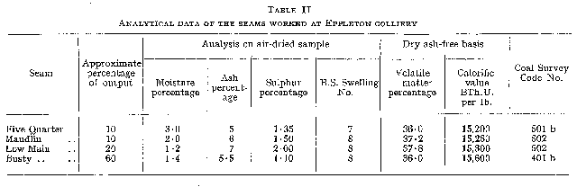
Four seams are worked at Eppleton colliery — the Five Quarter, Maudlin, Low Main and Busty — and the main characteristic of the coals is that they are very suitable for gas-making purposes. From Table II, which gives analytical data of the seams, it will he seen that they are strongly caking and have a high volatile content. Just over one-third of the output lies within a size range of ½ in. sq. to 3 in. rd.
The minus 3 in. material is separated from the run-of-mine coal supply to the picking tables, which are now three in number, by means of jigging screens which feed to a 36 in. Acco troughed belt conveyor. This raw-coal conveyor, which is some 104 ft. in length, runs at a speed of 300 ft. per min. and was originally on site to supply the dry-cleaning plant with 2 in.-0 material. Previous to the installation of the washbox and the treatment of material up to 3 in. size, the speed was 250 ft. per min., but this had to be increased to handle the heavier load, which at the peak point is 140 tons per hour. Drive for the conveyor is supplied from a 10 h.p. Metropolitan-Vickers electric motor running at 960 r.p.m.
From the 36 in. belt conveyor the 3 in. to 0 raw feed is passed to a surge hopper by means of a breeches chute, a device whereby the coal is unloaded at a point between the driving and tension ends of the conveyor, and consisting essentially of a receiving compartment and three chutes. As can be seen from the arrangement in Figs. 2 and 3, two of the chutes are positioned at right-angles to the centre line of the conveyor while the other is in line with the conveyor. By means of a pivoted plate door, the coal can be fed either into the surge hopper or back on to the belt. This latter facility is a means whereby, in the event of a breakdown, the 3 in. to 0 raw feed can bypass the washer and screens completely, being discharged from the belt conveyor direct into wagons.
The surge hopper, Fig. 4, a, which was built in the No. 2 Area Central Workshops, has a capacity of 35 tons. It was fabricated from ¼ in. and 3/8 in. steelplate and 3 in. by 3 in. angle iron, and is supported by 10 in. by 6 in. R.S.J.'s held in concrete blocks at ground level. However, previous to December, 1952, a feed hopper of 2-ton capacity had been in use, but, from experience, it was found to be insufficient to cope with peak loads. At the bottom of the surge hopper the 3 in. to 0 raw coal is fed on to a jigger-feeder, Fig. 4, b, also manufactured in No. 2 Area Central Workshops. This jigger, which is fabricated from 3/16 in. mild-steel plate throughout, was installed with the 35-ton-capacity surge hopper and is suspended from two 8 in. by 3 in. channel irons, at ground level, by means of four 3 in. by 5/8 in. mild-steel hangers. Movement at the rate of 200 strokes per min. is imparted to the jigger through connecting rods from an adjustable eccentric and sheave, Fig. 4, c, rotating at 182 r.p.m. The drive is provided by a 5 h.p. Metropolitan-Vickers electric motor running at 960 r.p.m. and transmitted to the eccentric by means of Vee belts.
The jigger feeds the 3 in. to 0 raw coal to a 36 in. Acco bucket elevator, Fig. 4, d, which is driven by a 15 h.p. Metropolitan-Vickers electric motor through an 8-in. "Radicon" reduction gear. This bucket elevator is completely enclosed in a mild-steel plate casing. When the 2-ton capacity hopper was replaced by the 35-ton hopper, the bucket elevator was lengthened by 9 ft. at the bottom. To accommodate the jigger and the added length of the bucket elevator. an excavation below ground level had to be carried out, the exact nature of which can be seen in Fig. 4.
Prescreening
The bucket elevator conveys the 3 in. to 0 raw feed up to the top of the building containing the picking tables where, as previously stated, is sited the washer proper. Here are two Symons F type highspeed, single-deck screens, Fig. 4, e, built by the Nordberg Manufacturing Company of the U.S.A. each having a 10 ft. by 4 ft. screening surface of ½ in. sq. crimped wire mesh. When originally supplied, the screens were equipped with 3/8 in. apertures and each was intended to take out 30 tons per hour of minus 3/8 in. raw coal from their 70 ton per hour feed.
The positive screening action of the Symons screens, which are totally enclosed in order to minimise the dust content in the surrounding atmosphere, enables them to be installed on a horizontal level plane. This proved a most advantageous feature when the Eppleton washery was installed because, as previously mentioned, the washery has been built into an existing building containing the picking tables, and the greatest possible use had to be made of the available structural features. As can be appreciated from Fig. 5, headroom was extremely limited so that the dimensions — especially overall height — of the sizing screens, which are nearly always found at the topmost point in a washery, was an important factor in their choice. This positive screening action is brought about by a constructional design which differs from the conventional type of screen and incorporates four major parts base, screening deck, balancing deck and drive unit. To the base, which is formed from channel iron, are welded pieces of angle iron having flexible supports for carrying the screening and balancing decks. These supports are formed from a number of thin, alloy-steel strips clamped together in units containing two, three or four strips set at an angle of 30 deg. with the vertical. The balancing deck consists of heavy bars at either side of the screen together with a small feed hopper clamped to these bars at the feed end of the screen. Attached to the screening deck, which is of a rigid box-type construction, are four flexible laminated strip-steel units, similar to those used for supporting the screening and balancing decks, and through which is applied the reciprocating motion for the screen from eccentrics mounted on a shaft. Each screen is driven through Vee belts by a 7 h.p. Metropolitan-Vickers electric motor mounted at the discharge end and running at 1,450 r.p.m., and this provides a speed of 650 r.p.m. at the screen driving shaft. These motors can be seen in the top right-hand corner of Fig. 6.
The principle of operation of the screens is that as the screening decks move in one direction the balance deck moves in the opposite direction, thus equalising the forces which are set up by the original movement. By this method the screens are given a wide amplitude of vibration at a high speed, providing for a rapid travel of the coal on the screening surface without any inclination of the deck.
Underneath the two screens are 8 ft. long conveyor pans which pass the minus ½ in. material through to a chute, Fig. 4, f, which in turn feeds on to an inclined 26 in. troughed-belt conveyor, Fig. 4, g, some 31 ft. in length and driven by a 5 h.p. electric motor. This conveyor carries the minus ½ in. material up on to the 36 in. troughed-belt conveyor previously mentioned, but at a point beyond the breeches chute. It is then discharged on to a bucket elevator and fed into the dry-cleaning plant.
The washbox
The 3 in. to ½ in. material which comes over the Nordberg screens passes down a launder, Fig. 4, h, into the washbox. At the point where the raw coal enters the launder it is made wet for washing by a stream of water which also helps to feed it into the washbox. Suspended over the launder is a magnet which removes any tramp iron from the raw coal feed. This magnet which can be seen in Fig. 6 was supplied by Electromagnets Limited, Boxmag Works, Bond Street, Birmingham, 19, and works on a 180 V supply.
The washbox, which is of the Acco standard jig type, is unique in being the first of this now popular type to go into production. Essentially, it comprises four standard units each containing washing compartments and an air compression chamber, together with two screw conveyors and elevators for the removal of dirt or shale. The washing compartments are covered with grids which can be seen in Fig. 6. The shale removal and discharge system is fully automatic, while a variable control over pulsations is made possible by the use of rotary valves driven through a variable-speed gear.
A diagrammatic illustration of the arrangement of the automatic control at each discharge end of the washbox is given in Figs. 7 and 8. Across the washing width of the box is a sill a (see also Fig. 9, a), which is arranged so that the clean coal passes over the top of it while the shale passes under. Surmounting the sill are the air chambers b (Fig. 9, b), which occupy only part of the washing width so that the coal can flow between them, and above the air chambers which open under the sill is a pipe c terminating at valve d. Two adjustable gates e and f are provided at the entrance to the shale discharge chamber. When the valve is closed, as in Fig. 7, the air is trapped in the chambers b and acts as a cushion, which effectively prevents the water in the chamber from pulsating, and from discharging. On the other hand, when the valve is fully open, as in Fig. 8 the air in chambers b can exhaust to the atmosphere and has unrestricted movement, so that the water in the chamber can pulsate freely. In these circumstances shale is discharged over gate e at each upward pulsation. An intermediate setting of the valve results in a discharge of shale appropriate to the particular setting.
The valve d is fitted with a light friction drive, which continually moves it very slowly towards the closed position. On the end of the valve spindle is a sprocket which is meshed with a chain carrying a stop g, the direction of motion being such that the stop gradually descends as the valve is being closed. The float j supports a rod, upon which is mounted a striker h. When the float rises to a sufficient height, the striker engages the stop and, overcoming the friction of the drive in the valve, opens it to a position as determined by the maximum rise of the float. Therefore, the valve which is continually driven to the closed position by the friction drive is also being continually set back towards the open position by the rise of the float, with the result that the position of the valve is relative to the stroke of the float. As the height to which the float rises in the float chamber is an indication of the resistance or quantity of shale in the bed, the amount by which the valve is kept open is directly related to this quantity of shale. The greater this quantity, the higher the float rises and the more open is the valve to allow greater pulsations in the washing chamber. The stop g and striker h can be set so that the valve begins to open only when a pre-determined thickness of shale bed is exceeded. A most important point in the setting of the washbox is the position of the gates e and f When completely automatic, the washbox discharges shale at the rate of entry with the raw-coal feed and ceases to discharge when the feed stops. A permanent bed of shale is held on the perforated plates even during periods of light load.
The operation of pulsating or jigging the products and wash water passing through the washbox can be readily controlled or adjusted to Acco short or long suspension air cycle and also to cycles similar to those of Baum and Bird. One of the rotary air valves as used for slow pulsation jigging is shown in Fig. 10; it is constructed mainly in special aluminium alloy. The rotor is ported in such a manner that the compressed air is controlled in each revolution to periods of inlet, expansion and exhaust. The valves now in use have been designed to give a quick lift to the bed of coal and shale in the washing compartment, followed immediately by either an extended suspension period during which the material is stratified, or to give a shorter expansion period at a speedier rate of pulsating.
The compressed air supply is obtained from a Bryan Donkin, three-stage turbo-blower, Fig. 4, j, running at 2,815 r.p.m. which delivers 2,000 cu. ft. of air per min. at a pressure of 3 lb. per sq. in. through a 10 in. diameter steel pipe main. The turboblower, which can be seen in Fig. 11, is driven through Vee belts and a flexible coupling by a 75 h.p. Metropolitan-Vickers electric motor running at 1,470 r.p.m. The air main from the turbo-blower enters an air manifold on the compression chamber of the washbox and can be controlled at this point by means of a butterfly valve, as shown in Fig. 12. A finer degree of control is available through screw-down plate type valves at each compression chamber, the handles for which can be seen in Fig. 12 and at Fig. 13, a. From the manifold the compressed air flows through the rotary valve and into the washbox compression chamber, Fig. 13, b, where it acts directly on the water and forces it downwards. Then for the period of expansion, the flow of air through the valve is stopped until the valve exhaust opens to atmosphere. The exhaust port is shown on the valve in Fig. 10, but from a study of Fig. 6 it will be seen that a cowling has been fitted to each of the four valves at Eppleton, preventing any disturbance of dust in the immediate surroundings. After exhaust of the air, the water in the compression chamber returns to approximately the same level as it was at the beginning of the cycle.
This downward and upward movement of the water in the compression chamber is immediately transferred to the washing bed in the washing compartment of the washbox. The speed of the air cycle can be varied between 20 and 60 r.p.m., normally 30 r.p.m. on long suspension cycle at Eppleton, through a Carter infinitely-variable speed gear incorporating hand control. Drive is provided from a 2½ h.p. Metropolitan-Vickers electric motor through the variable speed gear to a Crofts reduction gear which is coupled to the shaft of the first rotary valve by a chain and sprocket drive, and a tachometer with dial indicator is in use to show the speed of rotation of the rotary air valves. The motor with the various gearboxes can be seen in Fig. 12.
Coal and shale separation
The automatic control of shale separation, removal and discharge, coupled with the controlled pulsations enable the washbox, after setting, to treat feed fluctuations and peak loads, efficiently and automatically. At the varying duties the shale is removed and discharged constantly, not intermittently, at a rate equal to the amount of shale in the feed. This regular discharge of shale maintains regular conditions of pulsation and stratification of the products in the washbox and evens out the load of shale to be carried away.
Referring to Fig. 9, the 3 in. to ½ in rawfeed enters the first compartment of the washbox at c, where a primary removal of heavy shales, takes place immediately under the feed. This arrangement is most advantageous in view of the fact that the reduced quantity of products passing through the washbox can now be more easily stratified. Some of the fine shale is removed through perforated screen plates, Fig. 13, c, which have ¼ in. sq. holes, and settles down into the bottom of the washbox while the remainder of the large and fine shale, and middlings, is extracted at Fig. 9, d.
Drawings and Photographs accompanying the article


Article reproduced from a copy of the magazine held at National Mining Museum Scotland, Newtongrange, Midlothian.




 Contains public sector information licensed under the

