


 |

|

|

|
|
 |
 |
|||

March, 1954
A new Washbox at Eppleton - Part 2
This second part of an article describing a new type of Baum washbox a Eppleton colliery No. 2 (Mid-East Durham) Area of the Durham Division continues with a description of the shale and clean-coal discharge systems, the disposal of slurry, control and the results which have been achieved
The large shale, which of course is being removed at both the inlet and outlet ends of the washbox, is discharged into the base of an 18-in, perforated bucket elevator, Fig. 14, a, at each end of the washbox. The smaller shale which passes through the perforated plates and settles to the bottom of the washbox is also fed to these bucket elevators by means of two screw conveyors, Fig. 15, l. Drive for the screw conveyors is provided by two 5 h.p. Metropolitan-Vickers electric motors running at 1,430 r.p.m. through a chain and sprocket wheels and the shaft on which the screw is formed is mounted on ball bearings, outside the washbox.
The shale elevators are totally encased and watertight up to the level of the water in the washbox, 2 ft. 2 in. above the perforated plates. They are 30 ft. in length and each is driven by a 5 h.p., Metropolitan-Vickers electric motor through an Acco compact driving gear. The drive head, see Fig. 14 b, is arranged in such a manner that when tensioning the bucket chains, adjustments to the tumbler-shaft driving-chain are unnecessary. These two bucket elevators discharge onto a 24-in. troughed-belt conveyor, Fig. 14, c, which is driven by a 5 h.p. electric motor, and feeds a 5-ton capacity hopper fabricated from 3/8 in. steel plate and 3 in. by 3 in. angle iron. This hopper is fitted with a "Taylor" discharge door, as manufactured by James W. Ellis and Co. Ltd., Newcastle-upon-Tyne, 1, and discharges the shale into wagons. The hopper door, a diagrammatic arrangement of which is given in Fig. 16 consists of a rubber-faced belt a connected at one end to a steel drum b and at the other to a plate c which is part of a fixed frame d. The drum is mounted in a travelling frame e which also carries rollers f to support the belt, and the complete assembly is supported on four wheels g. At one end of the fixed frame there are mounted two 4-in, diameter pulley wheels h, one at each side of the frame, while two 4½-in. diameter pulley wheels j are mounted on a shaft k which is at the other end of the fixed frame. A length of wire rope is coiled for two or three turns around wheel j and the two ends fixed to the travelling frame. On shaft k is mounted a chain wheel which is hand operated.
The rotation of the drum winds up the apron belt while simultaneously the drum and the travelling frame are pulled towards the fixed plate c thus opening the discharge end of the hopper. Views of the hopper and Taylor door in the open and closed positions are given in Figs. 17 and 18 respectively.
Clean coal
The 3-in, to ½-in. clean coal from the washbox is delivered by means of a chute, see Fig. 15, m into a settling tank, n, and then removed by means of a 36-in, perforated bucket elevator, o, which allows the water to drain back into the tank. The bucket elevator is some 32 ft. in length inclined at 60 deg. to the horizontal and driven by a 10 h.p. Metropolitan-Vickers electric motor. A 3-in, diameter pipe also feeds into this settling tank from a point just below the perforated screens in the washbox and the suction helps to remove any material which has become jammed in the perforations. From the 36-in. bucket elevator, the coal is discharged onto a 26-in. colliery-built conveyor driven by a 5-h.p. electric motor and which is known as the "washed-coal conveyor".
This washed-coal conveyor feeds onto a Niagara high-speed, single-deck vibratory screen built by Niagara Screens (Great Britain) Limited, Enfield, Middlesex. The Niagara screen has a 48-in, by 96-in. screening surface of 1 in. sq. crimped wire mesh, and had already been in use at Eppleton as a doubledeck screen in connection with the dry cleaning plant, having been installed by Colliery Engineering Limited in 1936. It is driven by a 5 h.p. electric motor through a flat belt and pulley mounted on an eccentric shaft which transmits a constant oscillating motion to the cradle carrying the screening mesh. The direction of rotation of the shaft is counter to the flow of material, which causes the coal to turn over towards the flow as it rises and falls on the screen. The screening surface slopes at an angle of approximately 32 deg. from the feed to the discharge end, and gravity overcomes the tendency of the coal to travel up the screen. The products from the Niagara screen are classified as Trebles, 3-in. to 1½-in. and Singles, 1½-in. to ½-in.
From the classifying screen the Trebles are discharged onto a colliery-built 20-in, belt conveyor driven by a 5 h.p. Metropolitan-Vickers electric motor which feeds onto a boom loader, and this boom loader, which is essentially a belt conveyor driven by a 5 h.p. electric motor (also Metropolitan-Vickers), loads the Trebles into wagons for dispatch from the colliery. The Singles from the classifying screen are discharged onto another colliery-built belt conveyor, but of 24 in. width. It is also driven by a 5 h.p. electric motor, but unlike the Trebles conveyor, terminates in another type of breeches chute, Fig. 19, with twin spouts. With this arrangement, as shown in Fig. 20, it is possible to load two wagons at once and prevent spillage on the wagon-road while moving the wagons.
Slurry
Adjacent to the washed-coal tank, the purpose of which has just been described, there is situated a sump Fig. 15, p, into which there overflows from the clean-coal tank the water containing fine particles of coal in suspension. From this sump a single-stage centrifugal pump, Fig. 15, q which was supplied by Tangyes Limited, Smethwick, Birmingham, delivers 2,500 g.p.m. against a 30-ft. head to a slurry settling cone. The pump is driven through vee-belts by a 75 h.p. Metropolitan-Vickers electric motor, running at 1,470 r.p.m., and the installation can be seen in Fig. 21.
The slurry settling cone, Fig. 15, r, built by Holts of Leeds, has a capacity of 18,000 gal. and is 20 ft. in diameter at the lip, which is 32 ft. above ground level. A 10½-in. diameter pipe, Fig. 15, s, from the pump feeds the water and slurry into the top of a 2 ft. 6 in. diameter pipe situated centrally in the cone, the purpose of which is to prevent disturbance of the settling particles in the general body of the cone. At the bottom of the cone a short piece of steel pipe leads into a C.I. 3-way cock which is hand-operated and used to control the discharge of the slurry into wagons through a pipe as shown in Fig. 15.
A supply of water for the washbox is provided from the settling cone through a 10-in, diameter pipe, Fig. 15, t, and an overflow from the cone is taken to the sump by means of a 10-in, diameter pipe, Fig. 15, u. The make-up which is provided from the pit drainage water amounts to between 8,000 and 10,000 gal. per 24 hr.
Control
Operational
Control of the complete washery is effected from an 18-unit double-tier switchboard of "unit-type" design, and self-supporting sheet steel construction, as shown in Fig. 22, which was supplied by The Belmos Co. Ltd., Electrical Engineers, Bellshill, Lanarkshire, and the system is sequence-interlocked throughout, with an automatic warning system given through a klaxon horn. Each unit of the switchboard contains the various starters and isolators for different parts of the washery and the arrangement is as shown in Fig. 23. Unit 1 houses a kWh-meter, a transformer for the klaxon horn, and relays and timing mechanisms for the warning system, while the remaining units house the starters. In units Nos. 3, 9, 10 and 13 there are two starters over one isolator. The starters are of 30, 75 and 150-amp. rating and all are for direct on-line switching ; their control circuits are all at line voltage which is 500 V at 50 cycles per sec. The only remote control of the starters is by an emergency stop button for each, and normal control of the washery is effected from the switchboard by the Start-Stop buttons on each unit.
The starters are sequence interlocked in the order of Units 1 to 18 which means that the motors can only be started in that order. To do so, each start button must be pressed in turn, as the starting is not automatic. On the other hand, if the stop button of any starter is pressed the appropriate motor will stop and so will all the motors following in the sequence. As the order of the sequence is against the direction of flow of material through the washery, this system avoids piling up due to loading onto a stopped conveyor.
This sequence interlock is obtained by having on each contactor an auxiliary switch which is, normally open, and connected in series with the control circuit of the following starter in the sequence. In addition auxiliary switches are fitted to each isolator in these connections which come from the following unit, so that the contactor chamber is dead from all sources when the isolator is off. A rotary switch is also provided on each starter to cut out the sequence interlock when this is required for individual-unit test purposes.
The automatic warning by a klaxon horn which was previously referred to is a safety feature warning any person who may be on the plant that starting operations are about to be carried out. The motors cannot be started until 15 sec. after the warning blast is given. After that time the operator may start, stop and restart at will (within the limits of the sequence interlock system) for a period of 45 sec., during which time the klaxon horn continues to sound. When the 45 sec. period has ended, no further starting can be carried out until a further klaxon warning for 15 sec. has been given.
This arrangement is achieved by a relay in Unit No. 1, which has a 15 sec. and a 60 sec. timing mechanism, and the connections are shown in Fig. 24. The pressing of a master push button closes the relay, commences the action of the two timing mechanisms and causes the klaxon horn to sound. After 15 sec. the first timer closes a contact which energises a master, yellow-phase buswire running through the board. Each of the other units have their start button contacts connected between this master, yellow-phase buswire and their own blue phase so that any unit can be started while the master buswire is energised and its own isolator closed. As the contactor is closing, changeover auxiliary switches transfer the one side of the control circuit from the master yellow-phase buswire to the yellow-phase busbar of the unit. Therefore, after it is closed, the contactor is independent of the master buswire. Then, 60 sec. after the master button has been pressed, the second timber opens a contact which de-energises the relay, stopping the klaxon and de-energising the master buswire.
Performance
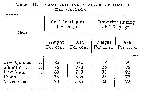
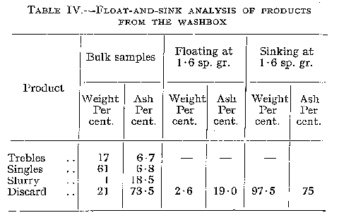
The efficient cleaning of coal in a washer is dependent on frequent sampling of the raw feed and the washed products, followed by laboratory determinations such as float-and-sink analysis and ash determinations. At Eppleton washery, the Area scientific staff take weekly samples of the coal being supplied to the washbox, see Table III, and of the products from the washbox, see Table IV when consignments for export are being executed, additional sampling is carried out. The washery staff are responsible for submitting a daily report of input and output tonnages to the Area Preparation Engineer.
Maintenance
Due to the washery functioning for 21 hrs. out of 24 hrs., one fitter for each of the three shifts is in attendance for maintenance purposes. No excessive trouble has been experienced beyond those such as are usually brought about by normal wear and tear. These entail, in the main, replacing the links and pins of bucket elevators, skid bars and wearing strips. Major repairs are, of course, carried out at week-ends when such operations as the changing of the perforated plate units in the washbox, which necessitates the draining away of the water, can be made possible.
Results
The installation of this new type of washbox at Eppleton has proved successful, as can be judged from the following remarks on the results which have been obtained. Definite and worthwhile savings in manpower have been effected, a greater quantity of high-grade coal has been made available and running-costs have been reduced.
Efficiency
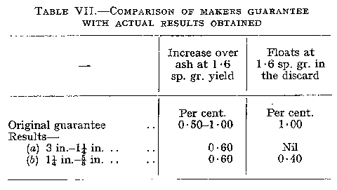
It is interesting to compare the maker's original guarantee with the results obtained from a test made on April 6th, 1952. This test was carried out over a period of four hours (11 a.m. to 3 p.m.) during which time samples of raw coal, washed coals and discard were taken. The average raw-coal feed to the washbox was 61 tons 7 cwt. per hr., and the rotary valves were set to give 48 pulsations per min. During this test period, the washbox operation was completely automatic.
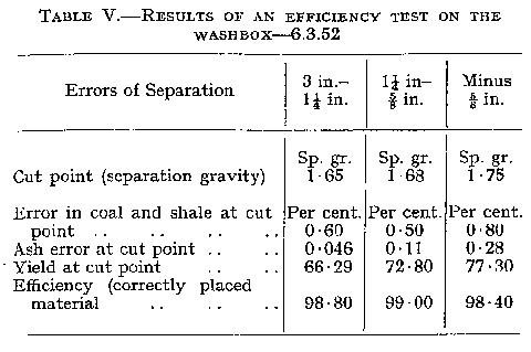
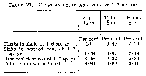
The results are given in Tables V and VI and from these figures it is revealed that the 3 in. to 1¼ in. coal was washed at 1.65 sp. gr., the 1¼ in.-5/8-in. at 1.62 sp. gr. and the minus 4 in. at 1.75 sp. gr. For the comparison of the maker's original guarantee with the actual results obtained see Table VII.
Manpower savings
When the washery was put into commission during November, 1951, the total man-power strength engaged on coal preparation at Eppleton colliery was reduced by seven. Originally, 16 men had been employed to cope with the coal passing over the picking table, on the site of which the washery now stands, and also for work in the dry cleaning plant. The decreased flow of coal to the dry cleaning plant, however, and the removal of the picking table, dispensed with the need for these men, and the washery requirements are only sufficient for two attendants plus one fitter per shift. Therefore, nine men are sufficient for the efficient operation of the washery in 21 hrs. out of 24 hrs. This saving of 35 manshifts per week is equivalent to £54 approximately, but apart from the monetary aspect, the substitution of mechanical cleaning for hand cleaning has eliminated the human element which unfortunately is always fallible. Also, these seven men have been released for more productive duties, and, in fact, the majority are now working underground.
Net savings
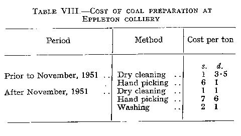
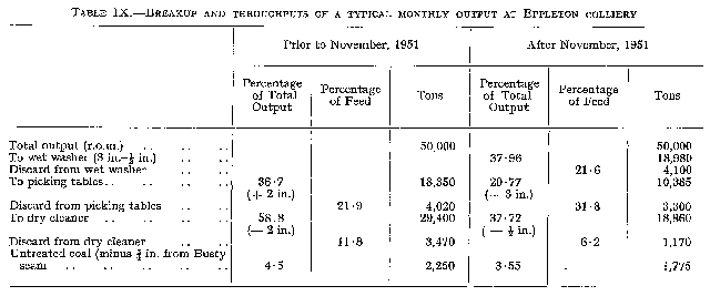
For a financial estimate of the final result which has been achieved through the installation of the washbox at Eppleton it is necessary to take into account costs such as wages, power, water, grease, oil, renewals, depreciation, and traffic charges for coal transport and dirt disposal. A comparison of the various costs pertinent to coal preparation at Eppleton prior to and after November, 1951, is provided in Table VIII, where the figures shown are calculated from salaries plus 9.27 per cent. for operating costs plus depreciation plus traffic charges for coal and dirt. From the various throughput figures as shown in Table IX it will be appreciated that a considerable financial saving is being made per month. From these two typical monthly outputs of 50,000 tons, it can be calculated that the cost of cleaning, say 95 per cent, of this run-of-mine coal prior to the installation of the washbox was £7,440, and after the installation £6,780. This is equivalent to a net saving of 3d. per ton of output.
Future developments
As stated previously in this article, the present washery comprising the ACCO washbox, Nordberg screens and Niagara screens, with all their ancillaries is only covering an initial stage in a long-term plan. A new shaft is being sunk which will replace the present coal-winding shafts at both Eppleton and Murton collieries the planned combined output is 7,000 tons per day. At the site of this new shaft a battery of coke ovens and a byproducts plant will be built, with a carbonising capacity of 1,000-1,500 tons per day. These coke ovens will take a considerable portion of the ½-in.-0 washed coal. A 750 t.p.h. washery will be erected to clean the total output.
Acknowledgments
For permission to publish this article we are indebted to Mr. A. H. Kellet, B.Sc. (Hons) (Min), M.I.Min.E., Area General Manager, No. 2 (Mid-East Durham) Area, Durham Division, National Coal Board. Also, we gratefully acknowledge the help received in the preparation of this article from Mr. A. McCombie, Area Coal Preparation Engineer, Mr. H. Hellewell, Area Chief Scientist and Mr. R. Greaves, Chief Mechanical Engineer at Eppleton Colliery.
Drawings and Photographs accompanying the article


Article reproduced from a copy of the magazine held at National Mining Museum Scotland, Newtongrange, Midlothian.




 Contains public sector information licensed under the

