


 |

|

|

| |
 |
 |
|||

September, 1947
Electric Winders at Sacriston and Kimblesworth
Drawings and Photographs accompanying the article
| Sample | Description |
|---|---|
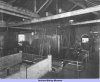 | Fig. 1 — The converted Robey/B.T.H. winder at Sacriston colliery |
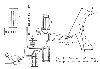 | Fig. 3 — Diagram of Robey-Crompton positive power brake |
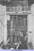 | Fig. 3 — General view of the brake gear of the Sacriston winder |
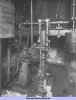 | Fig. 4 — A closer view of the Robey-Crompton positive power brake fitted to the Sacriston winder |
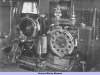 | Fig. 5 — Controlling the fast and slow braking device on the brake engine at Sacriston |
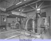 | Fig. 6 — Robey/B.T.H. electric winder at Kimblesworth colliery |
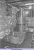 | Fig. 7 — Robey-Crompton positive power brake at Kimblesworth |
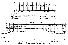 | Fig. 8 — Decelerometer records for normal braking on descending cage at Kimblesworth, with dead-weight brake (above) and positive power brake (below) |
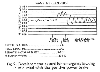 | Fig. 9 — Decelerometer record for emergency braking in mid wind with the positive power brake |
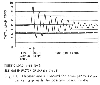 | Fig. 10 — Decelerometer record for emergency clow-banker trip with the positive power brake |
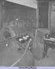 | Fig. 11 — Diver's cabin at Kimblesworth showing Robey control desk |
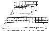 | Fig. 12 — Equivalent records to those given in Fig. 8 taken at Kimblesworth on the ascending cage |
Article reproduced from a copy of the magazine held at National Mining Museum Scotland, Newtongrange, Midlothian.




 Contains public sector information licensed under the

