


 |

|

|

|
|
 |
 |
|||

September, 1947
Electric Winders at Sacriston and Kimblesworth
A special feature of the new winders at these collieries is a positive power brake designed by Robey & Co. Ltd. To overcome the limitations of the normal weight-operated brake without sacrificing the principles of failing to safety.
Prior to 1st January Charlaw & Sacriston Collieries Co., Ltd., operated four collieries, at Witton, Sacriston, Shield Row, and Kimblesworth. These collieries were originally served by steam winders, but during the war the Company initiated a policy of replacing these machines, which had seen many years' service, by modern electric winders. At Sacriston and Kimblesworth the new winders are already in service, that at Sacriston having been changed over during Christmas, 1944, and that at Kimblesworth in July, 1946. The parts for the second winder for Kimblesworth colliery are now nearly complete and the machine is awaiting installation. All the mechanical portions of these machines have been built by Robey & Co., Ltd.
It is the purpose of this article to describe the winders at Sacriston and Kimblesworth, and in particular to give details of the construction and performance of the braking system. This system has been designed to overcome the drawbacks of the normal weight-operated brake but without sacrificing the principle of failing to safety. It is now fitted as standard to Robey winders under the name of the Robey-Crompton positive power brake. We described the principle of this brake in our June, 1942, issue, and we recently visited Sacriston and Kimblesworth collieries in order to form a personal estimate of the behaviour of the equipment in actual operation.
The Sacriston winder
The shaft at Sacriston is 637 ft. deep, the cages being double decked and carrying two tubs per deck. Each cage weighs 5,040 lb., the tare of the four tubs being 1,892 lb. and the coal load 4,256 lb. The rope is of locked-coil construction, 3¾ in. in circumference and weighing 3.83 lb. per ft. The winder is designed for a maximum cage speed of 20 ft. per sec. and an acceleration of 2 ft. per sec. per sec., giving a winding time of 43 sec.
This installation, which is depicted in Fig. 1, is actually a reconstruction of the old steam winder, and the old bedplate, drum and post brakes have been preserved. An extension to the winder house was first built on the left-hand side of the winder to accommodate the motor and reduction gear, and the necessary foundations were laid. The left-hand side of the engine was then dismantled, and a half-coupling was fitted to the drum shaft and faced up in position, the power for the turning operation being derived from the right-hand cylinder of the engine, which had been left for that purpose. The motor and gear were then lined up and coupled, and the right-hand side of the engine was dismantled and the arm of the crank burnt off.
All the electrical gear has been supplied by the British Thomson-Houston Co., Ltd. The motor is supplied at 2,750 V. 3 ph. 50 cycles and is a 300-h.p. continuous-rated machine running at 292 r.p.m., and driving through a 12½: 1 reduction gear. Control is through an air-break reversing main contactor and a liquid controller with automatic accelerating device. No reverse-current or dynamic braking is employed, full reliance being placed on the mechanical brake. Protection against overwind and overspeed is afforded by a Lilly controller. An interesting type of winding indicator is employed in which up-and-down fingers reproducing the cage positions are supplemented by a vernier dial giving a greatly magnified indication during the last revolution of the drum. This indicator can be seen in the distance in Fig. l.
The winding drum is 16 ft. 6 in. in diameter and has a moment of inertia of 100,000 lb. ft.2. The brake paths are 17 ft. in diameter with a 7-in, face, the brakes bearing over a vertical height of 8 ft. 6 in. As already mentioned, the old post brakes have been retained, but larger toggle plates have been fitted to the brake rigging, and the brakes have been faced with plain Ferodo linings, which have been found perfectly satisfactory whereas previous linings of zinc-bonded asbestos broke up.
Robey-Crompton positive power brake
Under the Safety Regulations a winding-engine brake must be provided with a deadweight which applies the brake in the event of failure of the brake-operating gear. This has led to the conventional design of gear in which the brake is applied by a falling deadweight and released by a brake engine which raises the weight. The operating characteristics of this type of brake are far from perfect, because the inertia of the weight causes an initial delay in coming into action followed by a snatch and probably a series of bounces. Such a brake not only tends to be rough in operation and difficult to control with prevision but introduces an element of danger. In the event of an emergency trip when nearing bank the initial delay in coming into operation reduces the safety margin — it may be vitally; again, the tendency to snatch may make a trip in mid-wind dangerous. Actually, of course, this liability to violent operation is minimised by introducing a dashpot element, but the improvement is effected at the expense of an increased delay before the brake makes contact. All these objections can be overcome by using a spring instead of a weight for the actual application of the brake, but a brake depending on a spring is liable to be put out of operation if the spring breaks. Further, the braking force will vary according to the clearance and amount of wear of the brake linings.
The Robey-Crompton brake has been designed to meet all the difficulties outlined in the preceding paragraph. An oil-operated brake engine is employed, but it is used not only to release the brake but also to apply it. The inertia associated with a weight is thus eliminated, and the brake comes into action promptly and progressively according to the position of the brake engine. To ensure the utmost smoothness in operation a spring cushion is introduced into the system, but it is not essential to the operation of the brake, and as the spring is arranged in compression a breakage causes it to make up solid and the brake continues to function. To comply with statutory requirements and also to act as a final safeguard, a dead-weight is held in reserve. This comes into action only if the oil pressure fails, in which event it exercises an overriding control. A trip called for by overwind, overspeed, electrical fault, or by emergency hand push applies the brake normally.
A diagram showing the principle of operation of the brake is given in Fig. 2. Oil under pressure is fed by duplicate pumps to an accumulator a which maintains a pressure of 120 lb. per sq. in. In the brake-engine b oil pressure is permanently applied to the top of the piston c, but pressure to the underside of the piston can be applied or withdrawn by means of a control valve d which is operated by the driver's brake lever. When the pressure below the piston c is withdrawn, the pressure in the upper part of the cylinder forces the piston down and applies the brake; when the pressure in the lower part of the cylinder is restored, the difference of area on the two sides of the piston due to the presence of the piston rod causes a resultant upward thrust which lifts the piston and releases the brake. An overtaking gear e connects the piston rod of the brake engine with the control valve d, its action being such that the brake engine comes to rest in a position exactly corresponding to that of the driver's lever.
The preceding paragraph relates to the normal functioning of the brake, but we now turn to emergency operation. The linkwork between the driver's lever and the overtaking gear is normally held by a solenoid or similar device f, but in the event of an emergency trip the solenoid is de-energised and a weight g carries the control valve down to the limit of its travel and applies the brake fully. To guard against the effects of a heavy brake application in mid wind, means are provided to restrict the speed of braking during the high-speed part of the wind but to leave it unrestricted when nearing bank. A valve is introduced into the exhaust from the control valve d which allows full-bore flow in one position and a restricted flow in the other. The opening of this valve is predetermined by a profiled cam which is driven from the drumshaft. The valve is partially closed during the fullspeed portion of the wind, so that the application of the brake is comparatively slow, but towards the end of the wind the cam progressively opens the valve so that very quick action of the brake is available, which is necessary as the cages approach the bank.
As the brake is applied by oil pressure a safeguard against loss of pressure — say, by a burst pipe or by a failure of the oil pump — is essential. This is provided by the deadweight h, which is normally held in an elevated position by the oil pressure acting on the underside of a piston i. As long as the deadweight remains in this position the brake engine can operate without reference to it, but if the oil pressure fails the weight descends and applies the brake. Thereafter the brake cannot be released until the oil pressure is restored.
A general view of the brake gear of the Sacriston winder is given in Fig. 3. The accumulator appears in the left foreground with the brake engine behind it, and the emergency deadweight can be seen to the right with its elevating ram standing above it at engine-room floor level. The oil pumps are off the front of the picture. A closer view of the brake engine is given in Fig. 4. The enlarged cylindrical portions of the pair of links connecting the engine to the brake rigging are the housings for the cushioning springs to which we referred earlier. In this installation the solenoid (f in Fig. 2) for tripping the brake has been replaced by a B.T.H. Thrustor, which performs the same office more smoothly and with a lower power consumption. It is hidden behind the small pedestal seen towards the left of Fig. 4, but its crosshead is just visible supporting a weighted lever which is coupled to the overtaking gear. This installation also incorporates a warning indication in the event of excessive brake wear. If this occurs the brake engine will overtravel on its downward stroke and make a contact which lights a warning lamp, showing that the brake needs taking up. The electrical conduit leading to this contact can be seen in Fig. 4 rising to the crosshead guide. The fast and slow braking device is not readily visible, but Fig. 5 shows the camgear at the base of the winding indicator. In this illustration the Lilly controller is on the right, and on the left is a rotating faceplate carrying adjustable camplates to engage the contact.
Kimblesworth winder
At Kimblesworth the shaft is only 458 ft. deep, but the loads are rather heavier than at Sacriston, being cage 6,720 lb., four tubs (two per deck) 2,464 lb., coal 4,928 lb. The designed acceleration and maximum speed are the same as at Sacriston, and the winder electrical equipment is identical. The Kimblesworth winder, however, differs from that at Sacriston in one important respect. After experience with the Sacriston conversion it was felt that the scheme had been hampered by the retention of the large low-speed drum and post brake of the old steam winder, and it was decided that the Kimblesworth winder should be new throughout. This permitted the use of a drum only 9 ft. in diameter and of a reduction gear of only 6.37:1. The moment of inertia of the drum is only 13,800 lb. ft.2 as opposed to 100,000 lb. ft.2 for the Sacriston drum, representing an important saving in power consumption during the accelerating period and in braking effort towards the end of the wind. Furthermore, modem brakes of the curved suspended type have been fitted, which give an even pressure over the whole of the brake area. These brakes act on 9 ft. by 6 in. brake paths over a vertical height of 7 ft. Centralised Tecalemit greasegun lubrication is applied to all bearings and pins of the brake rigging.
The Kimblesworth winder is illustrated in Fig. 6. The brake engine is identical with that at Sacriston, but it has been possible to arrange it somewhat more conveniently. A view of the equipment, including the pumps and oil tank, is given in Fig. 7. We must also mention the driver's control cabin which has been designed by Robey & Co., Ltd., and has been supplied in conjunction with both the winders described. As will be seen from Fig. 8, the keynote of the design is simplicity. Besides the usual levers for power, brake and men-coal, it carries a voltmeter, ammeter and oil-pressure gauge immediately in front of the driver, warning lights for failure of oil pressure and for slack brakes, pump switch, acceleration control, and emergency stop button. The shaft signals are mounted in the engine house in front of the driver's cabin as normally.
Braking performance
It so happened that during our visit to Kimblesworth, British Ropes Limited were conducting a series of decelerometer tests to determine the stresses incurred by the winding ropes, and in consequence we were afforded an excellent opportunity of observing the behaviour of the winder under both normal and emergency braking and of inspecting the resulting records. Although these records were obtained to investigate rope conditions they give a valuable picture of the character of the braking, and British Ropes Limited have kindly placed their material at our disposal for use in connection with this article.
The designed loading conditions have already been given earlier in the article, but they may be tabulated to the nearest quarter of a ton as follows :—
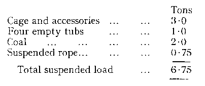
The loadings deduced from the accompanying decelerometer charts are therefore based on a static load for the ascending cage ranging from 6.75 to 6.0 tons and for the descending cage from 4.0 to 4.75 tons. Similar charts had already been taken with the previous winder equipped with normal deadweight brakes — the shaft conditions being identical — and the comparison between the two sets of records shows clearly the improvement effected by the positive power brake. In Figs. 8 and 12 are shown respectively the charts for the descending and the ascending cages, the record for the former deadweight braking being shown in each instance at the top and that for positive power braking below. For the descending cage the maximum kinetic load can be seen to have been decreased from 2.1 tons with deadweight braking to 1.0 tons with positive power braking, the corresponding decrease for the ascending cage being from 0.9 to 0.0 tons. Thus the effect of fitting this quicker-acting brake, so far from increasing the rope stresses as might be supposed, has substantially reduced them. Indeed, as will be seen from reference to the charts, the most severe kinetic load imposed by the brake — viz., 1.0 tons — is actually less than that of 1.4 tons imposed by the electrical gear during starting up. That this is no reflection on the electrical gear can be seen by comparison with the corresponding figure for the steam winder of 1.9 tons.
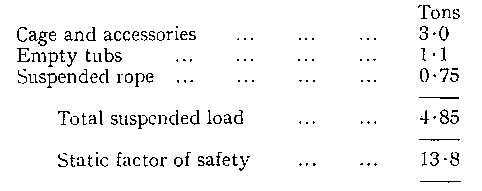
Several emergency-braking tests were also carried out, the smoothness of operation under these conditions being most noticeable. A trip from full speed in mid-wind — i.e., during the "slow-braking" period — brought the cage to rest in 1.8 sec. and imposed a maximum kinetic load of 2.5 tons, corresponding to a factor of safety of 9.3. The record of this test is reproduced in Fig. 9. A number of fast-braking tests were also taken on the slow banker, and for this purpose the normal load of 20 men was replaced by four empty tubs weighing 1.1 tons, the static loading conditions therefore being as follows :—
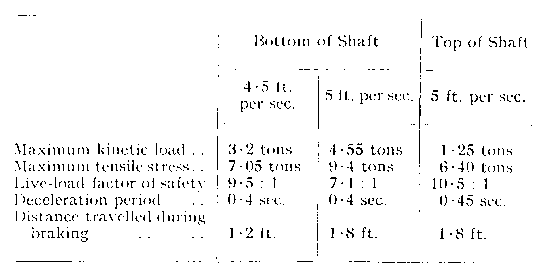
The following table gives particulars of three such tests, and in Fig. 10 is reproduced the record of the test given second in the table. This was the most severe test of the entire series, but even in this condition the live-load factor of safety was 7.1.
These tests suffice to demonstrate that the brake operates effectively, but does so without imposing any dangerous stress on the rope.
Acknowledgments
For permission to publish this article we are indebted to Mr. R. C. Elwes, Controller, Northern Division, No. 5 Area, Charlaw Unit, of the National Coal Board, and we would also thank Mr. J. B. Tindale, the Chief Engineer of the Unit, for valuable information and assistance.
Drawings and Photographs accompanying the article


Article reproduced from a copy of the magazine held at National Mining Museum Scotland, Newtongrange, Midlothian.




 Contains public sector information licensed under the

