


 |

|

|

| |
 |
 |
|||

April, 1935
Electrification of Ryhope Colliery - I
Drawings and Photographs accompanying the article
| Sample | Description |
|---|---|
 | Fig. 1 — Plan of the surface arrangements at Ryhope colliery prior to the reconstruction. Note the old winders and headgears, compressed-air plant, and the battery of boilers |
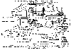 | Fig. 2 — Plan of the surface arrangements at Ryhope colliery after electrification and reconstruction. The boilers and most of the compressed-air plant have disappeared, and new headgears and winders have replaced the old. The fans are now electrically drivev. |
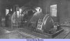 | Fig. 3 — Harvey pit winder |
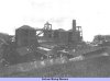 | Fig. 4 — Ryhope colliery prior to reconstruction |
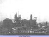 | Fig. 5 — West pit-head frame, June 9, 1932 |
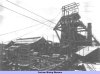 | Fig. 6 — Harvey and West Pit-head frame, early 1933 |
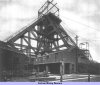 | Fig. 7 — View of the combined headgear for the Harvey and West pits as completed. Note right-angled constructiuon adopted to secure a site for the West pit winder. |
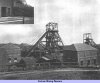 | Fig. 8 — General view of the Rhyope colliery after reconstruction, showing the Harvey and West combined frame on the left with the new South pit frame on the right |
 | Fig. 9 — Circuit diagram showing the scheme of control of the Harvey winder |
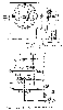 | Fig. 10 — General arrangement of the Harvey winder |
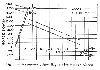 | Fig. 11 — Horsepower/time diagram for Harvey winder |
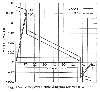 | Fig. 12 — Horsepower/time diagram for West winder |
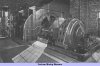 | Fig. 13 — General view of the South pit winding engine |
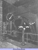 | Fig. 14 — Instrument pillar and depth indicator of South pit winder |
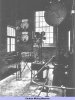 | Fig. 15 — View from driver's platform of West pit winder, showing Whitmore overwinder |
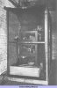 | Fig. 16 — Air-break contactor reverser for winding engine |
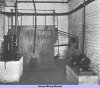 | Fig. 17 — Liquid controller for winding engine, with automatic accelerator on left |
Article reproduced from a copy of the magazine held at National Mining Museum Scotland, Newtongrange, Midlothian.




 Contains public sector information licensed under the

