


 |

|

|

|
|
 |
 |
|||

April, 1935
Electrification of Ryhope Colliery - I
A comprehensive scheme of reorganisation has recently been completed by the Ryhope Coal Co. Ltd. new headgears, winders, and a dry-cleaning plant have been erected and the entire surface and underground equipment electrified.
One of the most ambitious electrification schemes within recent years has been completed at Ryhope Colliery, Co. Durham. Three electric winders with their associated headgear have been erected, the surface plant has been electrified, an elaborate system of haulages has been installed together with electrically driven coal-face machinery, and compressed air has been eliminated except to serve a few districts that are nearly worked out. The colliery is about 80 years old, and the great age of some of the previous plant rendered its continued operation uneconomic. Investigation showed that electrification would justify its capital cost, and the actual saving has proved to be more than was originally estimated.
The early history of the colliery is interesting, particularly as it has a bearing on the present reconstruction. The first sod was cut on April 10, 1855, the mining engineer responsible for sinking and equipping the pits being the late John Taylor of Earsdon, an uncle of the present Chairman of the company, Thomas Taylor, Esq. Trouble with water was encountered, and the first winding engine had to be used for pumping, but the sand bed was reached in February, 1858, and the pit bottomed in 1859, proving the Maudlin seam 11 ft. in thickness. The first train load of coal was despatched on December 30, 1859, amidst much jubilation. Sinking of the second pit then proceeded, and was completed in October, 1867. The original shaft was known as the "South" pit and became the upcast; the newer shaft had four cages served by two winding engines on opposite sides of the shaft and known as the "West" and "North" (or "Harvey") respectively. To permit the four cages to pass each other, the shaft was widened in the middle and the wood guides splayed to conduct the outer cages to one side at meetings, the inner cages following a straight lead.
The old winding engines were particularly interesting, as they were of the beam type, built by Thos. H. Murray, of Chester-le-Street. They were housed in massive stone towers 80 ft. high, the drum being mounted in the top storey and driven from below through a crank and connecting rod by a 68 in. diameter by 84 in. stroke cylinder. Steam was supplied at 22 lb. per sq. in., and the engines ran at 18 r.p.m. Massive beams connected to the pit pumps, and a smaller beam served the auxiliaries. The winding ropes were flat, of 4½ in. by 1 in. section weighing 42 lb. per fm., and lasted only six to nine months. A balance-weight drum was keyed to the drum shaft outside the stone tower; this drum carried a weight of 10 tons made up of 35 fm. of flat chain lifting 72 ft. of short-link 2-in, chain which in turn supported a ring carrying six lengths of similar 2 in. chain. Motion of the winding drum was arrested by a band brake.
These old engines maintained their designed output of 700,000 tons per annum throughout their life. Nevertheless, their great age rendered them increasingly uneconomic to maintain and operate, a condition applying also to the headgears, which were of wood and had settled considerably.
The whole of the screening and washing plant was steam-engine driven, as was also the compressed-air plant, which furnished 13,000 cu. ft. per min. Steam for all these purposes was supplied by a battery of ten Lancashire boilers.
The Ryhope Coal Co. Ltd. were thus faced with the need for extensive reconstruction. The winders and headgears needed to be replaced. The extensive use of compressed air underground was proving wasteful, and it was desired to replace it as far as possible by electricity; this involved electrifying all underground haulages and pumps and using electricity for coal-face machinery. Furthermore, the boiler plant was old and was being pressed to the utmost, and if steam were to remain the motive power a new boiler plant would be necessary.
A comparison of costs between installing private generating plant and purchasing power from the public supply showed that the capital cost of the private plant weighed against its adoption, and the comparison was rendered still more unfavourable to the private plant because the colliery produces no brasses or inferior coal such as could profitably be consumed in a colliery boiler plant. It was therefore decided to dispense with steam and purchase electricity from the North-Eastern Electric Supply Co. Ltd. In following this course it was necessary to take into account the impending change of frequency from 40 to 50 cycles in this area. Some idea of the magnitude of the undertaking may be gathered from the plans of the surface arrangements before and after the conversion, as given in Figs. 1 and 2.
The Ryhope Coal Co. Ltd. then engaged the General Electric Co. Ltd. to act as main contractors for the entire electrification scheme.
Erection of new headgears and winders
The erection of the new headgears and winders proved a most difficult proposition owing to the necessity of keeping the old winders at work during the conversion, but careful planning enabled the work to be completed without the loss of a single ton of coal during the conversion. In outlining the plan of campaign, we would suggest constant reference to the surface plans, Figs. 1 and 2, and the progress photographs, Figs. 4 to 8.
The greatest problem was presented by the Harvey and West pit winders, and we will deal with these first. The original winders were in line on opposite sides of the shaft, and it was obviously impossible to erect both of the new winders on the sites of the old, as this would have interfered with output. A site for the new West pit winder was therefore cleared at right angles to the original line, and the new headgear built round the old. The old West winder was then dismantled to clear a site for the new Harvey winder, back legs being added to the new West headgear to form a combined right-angled headgear as depicted in Fig. 7. The way was then clear to dismantle the old headgear and the old Harvey winder.
The procedure will now be described in greater detail. It was, of course, necessary to design the new headgear so that it could be erected without interfering with the old, and to assist in this stage a wooden model was built, to a scale of ½ in. to a foot, showing the old headgear enveloped by the new. Having confirmed that work on these lines was practicable, work was commenced on the site on November 1, 1931, over 300 tons of rubbish having to be removed before digging could be started. Owing to the presence of buildings and plant it was impossible to set out direct centre lines, and a base line was laid by theodolite and the whole structure set off from side lines, a proceeding that proved absolutely correct on completion. Foundations for the main legs were commenced on February 1, 1932. A solid foundation was secured at a depth of 10 ft., and 220 tons of concrete were poured for the four foundations. The first section of the main legs, which are 2 ft. 3 in. square, was fixed on March 25, and riveting of the base of the legs started by the beginning of May, after which the kep girders were placed in position. To make way for the new headgear, the old cat gallows and jack pulleys were removed on May 21, 1932, and a commencement was made with the back legs on June 2, the situation a week later being depicted in Fig. 5. The new top plates and cathead girders were in place by June 27, and the back legs were completed by August l. The top portion of the Harvey pit back legs was commenced on October 17. On November 29 the West pit keps and baulks and the old wood framing were removed to make way for the new shaft framing. A month later the new keps had been finished, and work was in progress on the framework below heap level. The Harvey keps and framing were also erected at this time, but had to be placed temporarily 4½ in. out of true position to suit the old cages and guides.
The complete headgear, which is illustrated in Fig. 7, stands 103 ft. to the centre of the pulleys, which are 16 ft. in diameter. The pulleys for the Harvey pit are side by side, whereas those for the West pit are one above the other and at right angles to the others.
Foundations for the engine houses were commenced in the autumn of 1932. Erection of the West pit winder was started on October 1, 1932, and the engine run light by November 4; the Harvey pit winder was commenced on April 4, 1933, and completed on May 10. Ropes were run on to drums on May 27, and during the Whitsun week-end, June 3-6, the change-over was made to electric winding. The old pulleys, timbers, framework and bell baulks were removed in 18 hours, and the new ropes pulled over, the first rope being socketed by 9.45 p.m. on June 4 and the second by 2.30 a.m. the same night. From 8 p.m., June 5, to 2 a.m. following, the engine was run with coal and stone to stretch the ropes, after which coal winding was commenced with the original two-deck cages. On July 8 work was commenced on replacing the old cages by four-deck cages, which were ready for service by 10 p.m., July 9.
The South pit headgear was erected by somewhat similar methods, but was a much simpler proposition; the new winder was erected on the opposite side of the pit to the old winder, and both winder and headgear were virtually completed before it was necessary to interfere with the old gear, the change-over being effected by August 7, 1933. The South pit headgear is smaller than the other, standing only 78 ft. to pulley centres.
The new headgears and cages were designed and erected by Jos. Cook, Sons & Co. Ltd., acting as sub-contractors to The General Electric Co. Ltd.
Electric winders
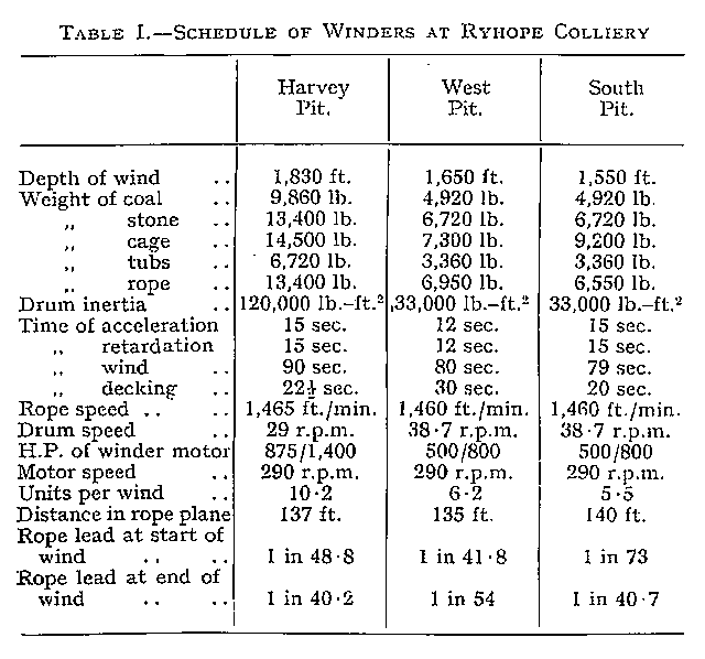
Schedules of the new G.E.C. winders are given in Table I. Of the three the Harvey pit winder, illustrated in Fig. 3, is the largest, being rated at 875/1,400 h.p. It has a 16 ft. by 11 ft. cylindrical drum, constructed of cast-iron cheeks made in halves, the joint being made at half arms. The brake paths are cast integral with the cheeks and fitted with mild-steel liners, spiral ventilating spaces being left between liners and castings. In place of the usual oak lagging, the drum shell is thickened and grooved to receive the rope, and is strengthened by compression rings inside the shell. Ferodo-lined straight-post brakes are employed, governed by a compressed-air brake engine. The drum is driven from the motor through double-helical single-reduction gearing, all bearings being of the ring-oiled spherical-seated type.
In view of the change of frequency now in progress in this area, the motor has a dual-frequency reconnect type winding. It is governed by a liquid controller in conjunction with an air-break contactor-type stator reverser, as illustrated in Figs. 16 and 17, the complete scheme of connections being given in Fig. 9. A master controller, coupled to the driver's hand-lever, makes forward or reverse connections immediately the lever is moved to either side of neutral, and energises an electro-pneumatic valve which closes the appropriate contactor in the stator reverser. Electrical and mechanical interlocks prevent either contactor being closed unless the opposing one is open, and a further safeguard is a potential transformer fed from the stator circuit and controlling an interlock which prevents one contactor closing until the arc formed by opening the opposite contactor has cleared. To ensure that the contactors close without shock, chokes in the air lines reduce the initial air pressure, but permit it to build up as soon as the contactors are closed.
The liquid controller is not connected directly to the driver's hand-lever, but is operated by a compressed-air relay which acts also as an automatic accelerating device. All the driver needs to do is to put his lever hard over, whereupon the compressed-air relay regulates the acceleration. to a predetermined value until full speed is reached. If it is desired to accelerate only to some intermediate speed, the lever is put into a corresponding position, and the compressed-air relay brings the winder automatically up to that speed. On the return movement to neutral the delay action is cut out, and the relay returns the liquid controller to the off position immediately.
Overwind and overspeed protection is afforded by a Whitmore overwinder fitted with an oil-dashpot slow-banking device as described in our April, 1933, issue. Operation of this gear releases a magnetic latch which trips the main circuit breaker and applies the brakes. A similar result obtains if the current or the compressed-air supply fails or if an emergency hand-lever is pulled over. Limit switches constitute a further safeguard against overwinding, and operate in conj unction with back-out switches on the master controller. Further electrical interlocks prevent closure of the main circuit breaker unless the driver's hand-lever is at stop, and prevent the emergency brake being released unless the service brake is first applied.
The South and West pit winders are built on precisely similar lines to the Harvey, but they are smaller, having 12 ft. by 7 ft. drums, and as their duties are very much alike they have been made duplicates. Views of these winders are reproduced in Figs. 13, 14 and 15.
Horsepower/time curves for the Harvey and for the West pit winders are given in Figs. 11 and 12. the diagram for the South pit winder being very similar to that for the West. With the original system of decking, the bottom deck of the cage was decked first, a procedure that entailed lifting the unbalanced weight of the rope between each decking operation. After conversion to electric winding the order was reversed, the comparative wattmeter curves showing a saving of 2½ kWh. per trip. It is intended later to adopt simultaneous decking and effect a still further economy.
Drawings and Photographs accompanying the article


Article reproduced from a copy of the magazine held at National Mining Museum Scotland, Newtongrange, Midlothian.




 Contains public sector information licensed under the

