


 |

|

|

|
|
 |
 |
|||
| Colliery Engineering | July, 1934 |
Static Dry Washer at Thornley Colliery
At the Thornley Colliery of the Weardale Steel, Coal & Coke Co. Ltd. a special gas coal is produced. Since this quality of coal must be both clean and dry, a Static Dry Washer has been erected to clean the small. The plant has a capacity of 100 tons per hour and treats coal of 2 in. to zero size. This coal is fed by star feeders to two tables whose air boxes are connected by ducts to one fan, it being arranged that when the pulsator of one air box is closed the other is open. In this way a single fan serves to produce the static pressure required for two tables. The clean coal from the first three cells is collected and conveyed by a Redler conveyor to be remixed with the hand-picked over 2 in. coal as run-of-mine gas coal. The middlings skimmed from the fourth cell is returned to the feed hopper for recirculation. The refuse passing under the last skimmer is discharged into an inclined chute and thence to a conveyor.
The two tables are parallel to each other and a steel sheet framework is built round them to retain the dust. Between the two tables a steel framework control room is built, isolated from the rest of the building by a steel dour. In the control room there are four controls, namely (1) a lever operating the butterfly valve dampers in the ducts to the air boxes for adjustment of the critical pressure; hand wheels controlling the variable speed gears for (2) the star feeds, (3) the eccentrics (table drive) and (4) the pulsators. The roof of the control room has a series of grills through which a slight positive pressure is maintained to prevent entry of dust into the room when the inspection covers are raised. This simple innovation has effected a remarkable improvement and has contributed considerably towards the removal of the dust nuisance. Opposite each skimmer is an inspection door with a canvas flap inside. These are used during adjustment of the air pressure to the critical value on starting up, and for general inspection. Once the pressure has been adjusted for a particular rate of feed, the control is mainly based on inspection of the refuse, the inclination of the discharge chute being increased to reduce the discharge of refuse if coal or middlings particles are found in it. This could result if the proportion of dirt temporarily decreased. To allow easy inspection of the refuse, a steel door in the metal casing opposite the end of the refuse-discharge chute is opened, when the refuse can be observed dropping from the chute to a conveyor below. The plant can be stopped with the bed maintained on the table, and on restarting, separation is immediately resumed.
Chassis. — The chassis is built up with double steel channels securely connected by angle cleats and gusset plates to top and bottom flanges. The inner (shaped) channel is illustrated in Fig. 2. Above this shaped channel is bolted timber framework of varying depth to allow for the steps between successive cells. Above the timber, the perforated plate, which is the deck of the trough, is mounted. The plate is in steel with 0.0625 in. round holes. 80 to the square inch, mounted above a 5 in. diamond lattice grid 1½ in. deep. In the older plants the deck sheeting was mounted into the permanent side members, but it is now bolted to 0.125 in. strips which are bolted to the side joists. The renewal of the decking, say every 9 months, is therefore simplified and takes considerably less time. The sides of the trough of 0.125 in. plate, with reinforced top edges, are bolted to angles above the joists.
Outside the shaped channels are similar but straight channels which end at the third skimmer, and are connected to cross channels and brackets to which hangers are connected for suspending the table. These hangers are of spring steel, 5 in. by ½ in. cross-section, and are supported from the steel girders in the framework of the building. The hangers near the third skimmer control the downward inclination of the table from the feed to the refuse end, the declination, normally ½ in. to 0.625 in. per ft., being adjustable by means of screw gear operated by handwheels.
The two channels and the cleats and plates are machined to give a good fit so as to preserve air-tightness. Below the lower gusset plate is bolted a 3 in. by 3 in. timber joist, the bolts passing through the lower wooden joist, and the lower flanges of the channels. The lower wooden joists are parallel for the whole length of the chassis, the spacing being the width of the first cell to allow the flexible connection to the air box to be made more simply, as a single vertical connection.
The two curved side channels on each side of the chassis are bolted together at 2 ft. 6 in. centres to preserve rigidity. From the end of the first cell to the end of the fourth, the sides of the chassis are covered with a sheet steel curtain, with chutes incorporated, for the discharge of the Upper layers of clean coal to the convevors on either side of the table. The assembled table, which is illustrated in Fig. 3, has a total weight of 2½ tons.
Drive. — It is reciprocated by a roller bearing eccentric, the eccentric rod being fastened into a steel casting so as to avoid side play of the gudgeon pin, which is of hardened steel and is adjusted by locking nuts to take up wear. Forced lubrication by grease gun, with channels through the gudgeon radially to the bearing surfaces, allow the clearance to be reduced and avoid any play. The eccentric has key-ways on the shaft so that the eccentricity can be adjusted.
The main motor, using about 70 h.p. for 2 tables of a 100 ton per hour plant, drives the single main fan, the two concentrics, the two pulsators and the two star feeders. All the drives except the star feeders are by Renold silent tooth and bush roller chains, totally enclosed, and all operate through reduction gear. The variable-speed gears are of the improved Reeves type, totally enclosed. From the main driving shaft there is an enclosed drive to the enclosed variable-speed gear for the eccentric drive near the steel framework of the feed end. The eccentric drive is steadied by two 2 ft. flywheels. From the main driving shaft there are enclosed drives down to the variable-speed gears of the pulsators and belt drives to the reduction and variable-speed gears of the star feeders. The star feeders have copper rivets for shearing when tramp iron is caught, but the belts are usually thrown off in such an event.
Pulsators. — The multiple pulsators are now fitted with eight vanes instead of six. The spindles are mounted in ball bearings and are separately driven through mitre gears from a vertical shaft in an enclosed side casing, the vertical shafts of the two pulsators being driven by a single horizontal shaft through a variable speed gear box. Each spindle can be replaced without taking down the casing. The spindles carry vanes, 6 to 9 in. wide, which rotate in machined ports. The two pulsators are synchronised so that when one is open the other is closed. The discharge openings of the pulsators are the full opening of the air box so that carefully-predetermined pressure waves can be produced at a specified rate. The air box is of all-steel construction with rubber jointings to preserve air tightness.
Dust Settlement. — The sheet-steel enclosure of the tables is continued from floor level to a suitable distance above the tables, where it finishes in close contact with the shell of the building. The dust which rises from the tables is settled by a simple and ingenious mist-spray system. Water from a tank controlled by a ball cock rises to the bottom of a series of water jets pointing upwards. Opposite each jet of the water pipe an air jet is inclined at right angles. Air is supplied from a fan capable of producing a pressure of 26 in. w.g., the discharge of air drawing the water from the jets and atomising it into a fine spray which diffuses throughout the chamber. The water mist settles on the dust particles which drop back on to the trough and the clean coal conveyors. The amount of moisture absorbed is too small to influence the moisture content of the product measurably. In the earlier plants only a single bank of mist spray pipes was used but double banks are now adopted. Their effectiveness may be judged by standing in the upper part of the building where only a fine "Scotch mist" is observed. There are 500 sprays on the Thornley plant compared with only 150 in the first plant where the method was. first applied. Nickel plated steel nozzles are used instead of the brass nozzles formerly used, to minimise wear.
In the upper part of the building two propeller fans driven by a single motor absorbing 7 h.p. are used to vent the upper atmosphere so that no back pressure disturbs the separation on the tables.
Results of cleaning
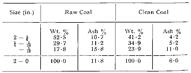
The Thornley plant was brought into full duty at the beginning of July of 1933. After the first month of full working a series of 17 tests taken during August and September showed the average ash content of the cleaned coal to be 5.94 per cent., the highest value being 6.45 and the lowest 4.80 per cent. This shows very consistent cleaning. The results in different sizes in one test are given in the table below.
The mixing of the 70 per cent. of cleaned minus 2 in. with 30 per cent. of hand picked oversize gives a gas coal of about 5.5 per cent, ash content. This may be compared with results from another colliery treating a similar coal in one of the earlier Static plants; here the average ash of the total gas coal is 6.3 per cent., so that an improvement corresponding to about 10 per cent, lower ash in the cleaned 2 in. coal is achieved by the later plant. The cleaning plant is housed in a brick-filled steel-frame building of pleasing appearance, a very considerable advance on the first units erected.
As previously mentioned, the clean coal is carried by Redler conveyors, an ingenious system which uses nonscraping links of short pitch (5 in.) which support the rough coal in a deep bed. The correct sequence and time lag of operation of the table and conveyors on starting up is controlled electrically, by an automatic contactor switch panel which is housed in an isolated fireproof switch house on the ground floor, only accessible to the skilled electrical staff (Fig. 6). In the mechanism room a push-button control panel is operated by the coal cleaning attendant for starting or stopping the motors.
The cleaning plant is operated by two men, the total power requirements are 170 h.p., and the total running costs including wages, renewals, and power are 1.9d. per ton of coal for the three months October, 1933, to January, 1934, a remarkably low figure. The capital cost of the plant, which was built by Huntington, Heberlein & Co. Ltd., was about £15,000.
Drawings and Photographs accompanying the article


Article reproduced from a copy of the magazine held at National Mining Museum Scotland, Newtongrange, Midlothian.




 Contains public sector information licensed under the

