


 |

|

|

|
|
 |
 |
|||

May, 1931
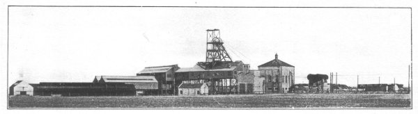
(Hauxley Colliery)
Broomhill Colliery
A Highly Mechanised Mine operated by Broomhill Collieries Ltd., is described.
The royalties exploited by Broomhill Collieries Ltd. are about 6,000 acres in extent and lie to the extreme north of the Northumberland coalfield. The northerly limit is bounded by the Hauxley Fault — supposed to have an upthrow of 140 fthm. — which entirely cuts off the workable seams of the coal measures proper. There are three shafts, two of which are used for winding coal, while the third, Newburgh, is used for pumping and ventilating purposes. In addition, as the seams are quite near the surface, a number of drifts have been put down to save travelling time for the men. The Broomhill shaft, situated about two miles west of Newburgh, is sunk to the Bottom seam and is 40 fthm. in depth. Hauxley, the third shaft, lies about a mile to the north of Newburgh and is 80 fthm. deep. This shaft lies within a few hundred yards of the coast and was sunk in 1926 to develop the undersea coal. It has a finished diameter of 18 ft. and has a brickwork lining, the insets, however, being of concrete.
Hauxley Colliery.
Being a new pit, unencumbered by those dictates of expediency which frequently confront managers who take over older workings, it has been possible to develop Hauxley colliery on the best modern lines. The shaft sidings are generously proportioned and the main undersea road has been made 10 ft. wide and 8 ft. high, thus affording excellent travelling height, haulage room, and ventilation space — all desiderata leading to economies, which, in the long run, more than compensate the extra initial cost of making a sound job at the commencement. A view of a portion of this road is given in Fig. 5. It will be seen that the supports consist of arched steel girders lagged with a combination of brick walling and timber. The arches are of 5-in. B.E.S.A. section and the timber lagging struts are thoroughly impregnated with creosote before being inserted. A similar type of support is used for the branch roads, which are made 8 ft. wide by 7 ft. high, the girders being of the same section as in the larger road. Up to date about 3,000 yards of roadway have been supported in this way, the results having been very satisfactory indeed.
It will be seen that the electric cables are suspended from the arched girders with special carrying clips. The clip (Fig. 2) consists of two members, which embrace the flange of the girder and are held together by means of a cotter or dog spike passing through a loop. The loop is spot-welded to one member to prevent detachment. When the cotter is inserted and driven tight, the two parts of the clip are drawn together and provide a quick and secure attachment. A modified form of this clip (Fig. 1) is also in use as a support for bell and telephone wires. This clip has an elongated base portion, on which are mounted two insulator bobbins. The bell wires are attached to the bobbin by the usual method of a binding wire being passed round the bobbin and the bell wire.
This method of supporting cables and bell wires by means of efficient clips has obvious advantages, the chief of which being (1) quick attachment and detachment with requisite degree of reliability, (2) cables can be suspended with absolute security and in any desired position on the roadway, and (3) in the case of the bell-wire clip, the insulators are at fixed centres, thereby ensuring a perfectly uniform line with the wires at a definite distance apart. The clips are made by Messrs. Robert Morris, Farnworth, Bolton, and marketed by Messrs. E. Angus Leybourne, of Newcastle-on-Tyne.
Careful attention has also been given to the track, which is laid with B.E.S.A. rails weighing 30 lb. to the yard and laid on steel sleepers of the clip and bolt type. The gauge is 2 ft. Although desirable in itself, this weight of track has been made additionally necessary in view of the large tubs which have been introduced, and are gradually replacing tubs of 10 cwt. capacity. The new tubs have a capacity of 25 cwts. and are equipped with 14-in, roller-bearing wheels, the tare being 12 cwt. The bodies were supplied by Robt. Morris Ltd., of Bolton, the roller-bearing axles having been manufactured by Robert Hudson Ltd., of Leeds. Views of these tubs are given in Figs. 12 and 15, from which it will be seen that the wheels are deeply recessed into the body, so that the height from rail level, 3 ft. 7 in., is by no means excessive, the design lending itself to a maximum coal carrying capacity. The length over the buffers is 7 ft. 10 in. and total width 2 ft. 9 in. The introduction of such a large tub marks a novel departure from the usual practice in the Northumberland and Durham coalfield, where one frequently comes across tubs — a legacy from bygone generations of engineers — with a capacity as low as 8 cwts. The larger tub has much to commend it, particularly where machine mining is in vogue, since it reduces the amount of manhandling required and also effects economies, in relation to the quantity of coal carried, in both power and space. Roller bearings, too, add their quota to the reduction in power consumption and entail infinitely less labour as regards lubrication. Nor is their upkeep anything like so considerable as many engineers suppose, experience at Hauxley having proved them to give very satisfactory service in this respect.
As far as possible motors for the haulages have been restricted to three standard sizes — 30, 60 and 110 H.P. The haulages themselves are of the main-and-tail type, and for the most part were supplied by M. B. Wild & Co. Ltd., the motors having for the most part been provided by Metropolitan-Vickers. A view of a typical unit is given in Fig. 14, which shows an M. B. Wild gear, driven in this case by a 110-H.P. motor of B.T.H. manufacture. For working landings and auxiliary purposes, 4½-H.P. Eickhoff and M. B. Wild units are in use, equipped for either the single-rope or endless arrangement as the circumstances demand. With the aid of these it has been possible to eliminate a great many ponies from the pit.
An improvised haulage of some interest is illustrated in Fig. 8 ; this shows the electric motor of an old Diamond coal-cutter rigged up to drive an endless gear, the arrangement working very well indeed.
Trunk Conveyor System at Hauxley.
The Bottom seam at Hauxley has a section ranging from 1 ft. 9 in. to 3 ft. 3 in., the floor consisting of from 3 to 5 in. of fireclay, and the roof varying from shale to post (sandstone). The gradient is as much as 9 in. to the yard. The coal is won from conveyor faces, arranged as shown in Fig. 3, and having a standard length of 80 yards. Coal from the face conveyors is first delivered to the gate conveyors and then to a main trunk conveyor, which brings it to the loading point on the roadway. In this way the output from a number of faces can be simultaneously converged on one loading point, the limit being determined by the capacity of the mothergate conveyor. The workings are thus concentrated to the highest possible degree and the coal handled entirely by mechanical means and discharged to one point. A further advantage is that continuity of output is secured by working the different faces in different shifts. Belt conveyors are used on the trunk roads, 20 in. wide for the gates and 26 in. wide in the main trunks. The 20-in. conveyors are carried to a maximum length of 300 yards, the limit in the case of the 26-in, belts being 400 yards. A view of a 26-in, main trunk belt delivering into the pit tubs is given in Fig. 7. while Fig. 9 shows a 20-in. gate belt delivering into the trunk conveyor. Both these conveyors were manufactured by the Mining Engineering Co. Ltd., of Worcester, whose belt conveyors are standard throughout the colliery for this class of work. Shaker conveyors are the general rule for face work, although a few Clephan belt units are also in service where the gradient conditions are not suitable for shakers. All the shakers are of Meco or Mayor & Coulson manufacture, the delivery end of a typical unit, in this case by the latter firm, being given in Fig. 10.
The coal is undercut to a depth of 5 ft. with Anderson Boyes machines, and Siemens-Schuckert electric drills are used for the shot-holes in the face. Electric drills are also in service for stone work, in this case the Monarch electric drill, supplied by Hugh Wood & Co., being used. This is a rotary drill, developing 3 H.P., the cutting speed being regulated by slipping the thread. It is stated to give as high a drilling speed as the compressed-air percussive type, and as it is provided with a twist steel, the drill cleans itself and there is no dust nuisance.
The irregularity of the roof at Hauxley has required rather special treatment to be given to the matter of roof support. In an ordinary way, steel supports would be used (as is the case at Broomhill Colliery), since the roof pressures are considerable, but it is impossible to accommodate a standard length of steel prop to such varying roof heights on account of the expense and wastage of cutting. Consequently, wood props are used of enhanced thickness, a 4-ft. prop being sawn in two to give, say, a 2-ft. prop a thickness of 4 to 5 in. instead of the normal thickness of 2 to 2½ in. These are used in conjunction with corrugated-steel crowntrees 6 ft. long, the first row of props being set back 2 ft. 6 in. from the face, thus allowing ample room for the cutter to pass. The 2-ft. 6-in. strip of roof next to the face is not left unsupported, however, as the crowntree projects over the prop and acts as a cantilever. The second row of props is set at the goaf ends of the crowntree, thus leaving a 2-ft. 6-in, space for the conveyor. This arrangement will be clear by reference to the diagram in Fig. 4.
Drawings and Photographs accompanying the article


Article reproduced from a copy of the magazine held at National Mining Museum Scotland, Newtongrange, Midlothian.




 Contains public sector information licensed under the

