


 |

|

|

|
|
 |
 |
|||

May, 1930
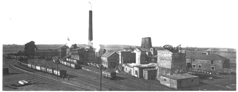
Pelaw Main Collieries
Brief particulars are given of the Reconstruction Scheme initiated by Pelaw Main Collieries Ltd., situate at Birtley, in the County of Durham.
Consisting of six pits having an aggregate output of 1,300,000 tons per annum, the group operated by Pelaw Main Collieries Ltd. was acquired just before the difficult times which arose through the 1926 strike. At the time of taking over, the output of the entire group was only about 2,500 tons per day, and it says much for the energy and skill which have been put into the reorganisation work that, in spite of the adverse trade conditions which have prevailed since 1926, this output has been more than doubled. Nor has the reconstruction work ceased, for the owners are continuing to improve on what they have already done by adopting newer methods of technique wherever practicable. Before we speak of this work, however, we wish to place on record our thanks to Mr. H. R. Hornsby, the agent of the company, for giving us facilities to inspect the collieries and publish our article, and we are further very sensible of the help we received from Mr. G. W. N. Harrison, Chief Engineer of the company, and his staff, which we also gratefully acknowledge.
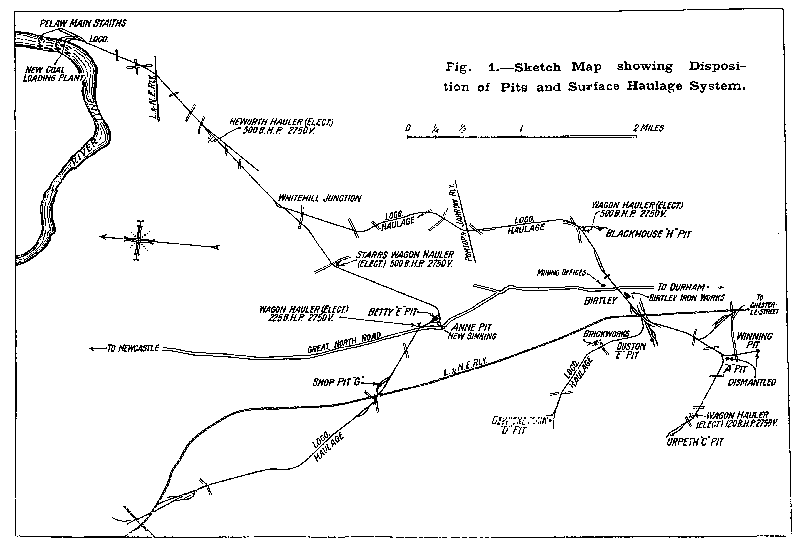
Before describing the reconstruction work in detail we would refer our readers to Fig. 1, which gives the disposition of the pits and shows the interconnecting railway lines for the surface transport of the output. The coal is conveyed to two main points ; that for shipment being delivered to the company's own staiths on the River Tyne, and that intended for inland consumption delivered to the L. & N.E.R. at Dunston and Birtley, but only a very small proportion of the output is handled by the latter method.
The undulating nature of the country has precluded the adoption of locomotive haulage on the whole of the company's private system, and the coal is consequently transported by a variety of methods — locomotives, rope haulages and self-acting inclines all taking their part in the scheme according to the dictates of the gradient. If the system is novel it is none the less economic and works very smoothly indeed. The reconstruction work done here has been to electrify the various haulages which were formerly operated by steam and involved small isolated boiler plants working under anything but favourable conditions. The whole of the Chaldron type of wagons have been replaced by 10½ ton treble wagons, and the majority of the old and dilapidated locomotives have been replaced by up-to-date ones.
Quite recently the shipping facilities have been entirely modernised, new staiths and shipping-loading plant having been erected by F. Turnbull & Company, of Newcastle-on-Tyne. These include a steel bunker into which the coal is delivered direct from the railway trucks, two of the latter being unloaded at once, and a system of belt conveyors capable of loading vessels at the rate of 600 tons per hour.
The discharge end of the loading conveyor is supported by a travelling tower which traverses the jetty, so that no time is lost in moving the ship in order to place the hatches in a suitable position for receiving the coal.
The loading end can be readily moved across the vessel and has in addition a wide range vertically to suit any size of vessel at all states of the tide. The loading chute at the end of the conveyors is of novel construction. It can be rotated horizontally in a complete circle and maintains a constant running angle automatically, no matter at what angle the conveyor may be inclined. For bunkering, this device is especially useful, as the temporary wooden chutes often erected over the bunker hatches for guiding the coal can be dispensed with, thus greatly reducing the time required for bunkering vessels.
The whole of the operations for working the plant are under the control of the brakesman in a control cabin attached to the movable tower which commands a full view of the ships deck.
The Central Power Plant at Ouston "E" Pit.
In power matters the guiding principle has been to suppress the smaller isolated steam plants, reduce the compressed air consumption to the smallest practicable limits and substitute electrical energy wherever possible. To this end new generating plant has been erected at the Ouston "E" Pit and the boiler house re-equipped, an old battery of Lancashire boilers having been scrapped and water-tube boilers substituted. Two of these are Babcock units, having an evaporative capacity of 14,000 lb. per hour and fitted with Crosthwaite mechanical stokers to enable low-grade fuel to be burnt. More recently two boilers of the Woodeson type, manufactured by Clarke Chapman & Co. and having a capacity of 15,000 lb. of steam per hour each, have been added. These are equipped for firing with pulverised coal, as will be gathered from Fig. 2. Fine coal (under 1/8 in.) is brought direct from a Birtley dry-cleaning plant to the pulverisers by means of a suction conveyor, so it will be realised that the very latest methods have been adopted wherever they promise of effecting economies. The suction conveying plant has a capacity of 5 tons of dust per hour and was supplied by H. J. H. King & Co. Ltd., of Nailsworth. Should an insufficient supply of fuel be available from the dry-cleaning plant an arrangement is provided by which small coal can be sucked from trucks. A new water-softener plant has also been put into commission, this being of the lime-soda type supplied by United Water Softeners Ltd.; having a capacity of 5,000 gallons per hour, and reduces the hardness from 18 to 2 degrees.
Electrical generating plant consists of a 750-kW. mixed pressure Parsons set and a Belliss / English Electric set of 1,000-kW. capacity. Both generate 2,800-volt current at 40 cycles and run in parallel with the Durham County Electrical Distribution Co.'s mains, whose incoming supply is stepped down from 20,000 volts to 2,800 in their own transformers. A view of the Reyrolle switchgear is given in Fig. 8 ; the board to the left controls the County supply while that facing the camera controls the distribution to the pits. Two voltages are in use, the higher (2,800 volts) being supplied to the winder, fan and standby compressor, and to the underground pumps and main haulages, while the lower voltage (440) serves the smaller surface motors and the inbye plant. Several transformers are employed to step down the high-tension supply to 440 volts, viz. 625 kVA., 250 kVA., 150 kVA. and 100 kVA., according to convenience, and all these are supplied by the English Electric Co. Ltd. Further transformers of 20-kVA. capacity each reduce the 440-volt current to 110 volts for lighting purposes these are situated at the surface and underground. A 2,800-volt ring main connects the "C," "D," "F," "H" pits and railways to ensure continuity of supply. The compressed air supply is provided by two horizontal steam-driven compressors by Walker Bros., of Wigan, each capable of delivering 4,500 cu. ft. of air per min. at 75 lb. pressure. Standby plant consists of a Belliss two-stage compressor having a capacity of 2,600 cu. ft per min. direct-driven at 260 r.p.m. by a Bruce Peebles slip-ring motor developing 455 H.P. Steam consumption in the power house is measured by Electroflo recording and integrating instruments, and a Bailey pressure recorder is also in use.
The main shaft is 14 ft. in diameter and has recently been provided with a new winding engine. This was supplied by John Wood & Sons Ltd., of Wigan, who effected the erection work in record time. Owing to the congested nature of the site no alternative position was available for this equipment, which had thus to he erected on the ground occupied by the old winder. Commencing on a Friday night just before the Christmas holidays, the old winding engine was dismantled after drawing the last shift and the foundations cleared by the Monday morning. Working continuously night and day, the new engine was erected ready for duty on the following Monday morning. A view of the equipment is given in Fig. 12 ; the cylinders are 22 in. in diameter and have a 48 in. stroke and are provided with main valves of the balanced-piston type, with cut-off valves of the drop pattern controlled by a centrifugal governor. The parallel drum is 11 ft. in diameter and is lagged with oak ; steam-operating post brakes are fitted and also the makers' steam reversing gear, which incorporates floating valves and an oil cataract cylinder. Overwind prevention equipment consists of a "Visor" gear.
The upcast shaft is now being equipped for winding men, and a new electric winder (Fig. 13) is in course of erection. This comprises an 8-ft. parallel-drum gear driven by a 2,750-volt, 175-H.P. motor ; John Wood & Sons Ltd. having been responsible for the mechanical parts and Metropolitan-Vickers Electrical Co. Ltd. for the electrical. The shaft has a diameter of 12 ft. and is about 80 fthm. in depth, and has been fitted out to relieve the congestion on the main winding shaft. Suitable air locks are being provided for the passage of the men, and rope guides installed.
The ventilating plant has also been overhauled and an old type steam-driven Waddle fan, 35 ft. in diameter, has been replaced by a Sirocco unit capable of passing 160,000 cu. ft. of air per min. against a 4-in. water gauge. This has a speed of 185 r.p.m. and is driven through eight 1-in. Kenyon ropes by a 150-H.P., 2,750 volt motor of Metropolitan-Vickers manufacture. A 25 in. diameter Sirocco auxiliary fan has also been installed in the Busty seam capable of delivering 44,500 cu. ft. against a 2-in. w.g. pressure. This is belt driven at a speed of 420 r.p.m., a Metropolitan-Vickers motor again being in service.
Formerly the pumping duty was undertaken by air-driven pumps, but following the policy of eliminating compressed-air equipment as much as possible, an 8-stage Mackley turbine pump has been substituted, driven by an 85-H.P. motor. This delivers 300 g.p.m. against a total head of 495 ft.
Drawings and Photographs accompanying the article


Article reproduced from a copy of the magazine held at National Mining Museum Scotland, Newtongrange, Midlothian.




 Contains public sector information licensed under the

