Museum Entrance Museum
Museum
Friends of Durham Mining Museum
Events Calendar
e-Books and Books for sale
Photograph Gallery
Document Archive
Main Document Archive
Newspaper Articles
Local Record Extracts
D.M.A. Document Archive
Transactions of I.M.E.
Miners' Welfare
N.C.B. Archive
The Colliery Engineer
The Colliery Engineer - Main Index
The Colliery Engineer - Subject Index
The Colliery Guardian
Mine & Quarry Engineering
Mining Journal
The Science and Art of Mining
Coal Magazine
Coal News
Coke and Gas
Master Name Index
What's new in the site
Mining
Mining History
Colliery Index
Colliery Maps
Company Overviews
Who's Who
Mineral Information
Managers Certificates
Educational Material
Bibliography
Statistics
Workers/Employee Lists
Notes for Family Historians
War Service information
Disasters
Disaster Reports
Names of those killed
Disasters in the 1700s
Disasters in the 1800s
Disasters in the 1900s
Memorials
Awards for Gallantry
On this day ...

Links to other sites of interest
Industrial Heritage Days Out
Former www.pitwork.net web site

Index to site

Contact and address details

Share Page with Social Media

Share on Facebook

Share with Reddit

Share on Delicious

Title Prev Page Return to Index Next Page Title
Masthead
April, 1930

Lord Londonderry's Vane-Tempest Colliery

Drawings and Photographs accompanying the article

Sample Description
Thumbnail Vane Tempest Colliery
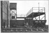
Thumbnail Fig. 1 — Hoist and Gantry for disposal of Ashes
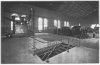
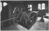
Thumbnail Fig. 2 — View of Power House, showing Compressor and Turbo-Alternator with new Plant under Construction in Background
Thumbnail Fig. 3 — 6,000-g.p.h. Water-Softening Plant
Thumbnail Fig. 4 — 1,000-kW. High-Pressure Turbo-Alternator Set
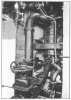
Thumbnail Fig. 5 — Jet Condenser for High-Pressure Set
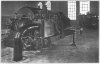
Thumbnail Fig. 6 — Robey Winder for No. 1 Pit
Thumbnail Fig. 7 — Picking Belts, showing Centre Channel for Dry-Cleaned Smalls
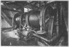
Thumbnail Fig. 8 — Capstan Engine in Basement of Winder House
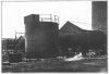
Thumbnail Fig. 9 — View of Screen House and Gantries, showing Dust Collectors
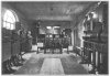
Thumbnail Fig. 10 — Interior of Surface Substation
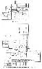
Thumbnail Fig. 11 — Drawings showing Layout of Screening and Dry-Cleaning Plant
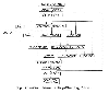
Thumbnail Fig. 12 — Flow Sheet of Dry-Cleaning Plant
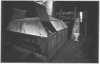
Thumbnail Fig. 13 — One of the Separators, showing Sectionalised Dust-Tight Hood
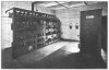
Thumbnail Fig. 14 — The Contactor Panel and Switchgear for Controlling Screen and Dry-Cleaning Plant Motors
Thumbnail Fig. 15 — View of Separator with Hood Removed

Article reproduced from a copy of the magazine held at National Mining Museum Scotland, Newtongrange, Midlothian.


mail
Mail:
Webmaster
Back
Back
Home
Home
Open Government Licence   Contains public sector information licensed under the Open Government Licence v3.0.

Copyright © 1999-2024 by The Durham Mining Museum and its contributors
Registered Charity No: 1110608
Page last updated: 17 Jan 2023

Privacy Policy
 
Terms & Conditions
 
Search
Search
Print
Print