


 |

|

|

|
|
 |
 |
|||

April, 1930
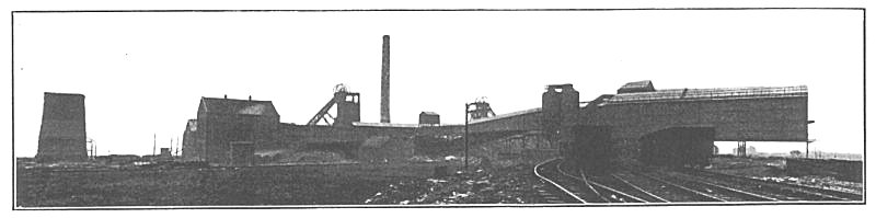
Lord Londonderry's Vane-Tempest Colliery
Brief details are given of the Surface Equipment installed at the two New Pits sunk by Londonderry Collieries Ltd.
Readers will no doubt recall that this new undertaking of the Londonderry Collieries Ltd. has already been brought to their notice in connection with the boring operations incidental to the freezing process and in connection with the freezing process itself. A brief account will now be given of the surface equipment and preliminary exploitation work. For permission to visit the colliery in order to obtain the necessary data for this article we are indebted to Mr. Malcolm Dillon, the Managing Director of Londonderry Collieries Ltd., whose good offices in this connection are gratefully acknowledged.
Two shafts have been sunk 200 ft. apart and having finished diameters of 21 ft. They have depths of 2,116 ft. and 1,895 ft. respectively, and are tubbed through the water-bearing Magnesian Limestone and Yellow Sands from 68 ft. to 598 ft. below the surface, the lining in the underlying Coal Measures consisting of 9-in, brickwork. Five important seams of coal are traversed, their depths from the surface being as follows :-
| Five Quarter | 239 | fths. |
| Main Coal | 265 | |
| Maudlin | 282 | |
| Low Main | 287 | |
| Hutton | 307 | |
| Harvey | 336 | |
| Busty | 350 |
Both the Maudlin and Hutton seams have been worked before from Seaham Colliery, the workings penetrating about three-quarters of a mile under the sea. From the more advanced places the coal had to be transported nearly three miles underground to the Seaham shafts, so that the necessity for the new pits will be obvious. The other seams mentioned are entirely virgin and, of course, contain large reserves. It is intended to produce some 3,000 tons per day in the immediate future, the Maudlin and Hutton seams contributing to this output in more or less equal ratios. The Harvey and Busty seams will not be exploited for some time.
Both headgears are of the steel lattice-girder type and stand 80 ft. high from the base to the centre line of the pulleys. They were erected as soon as the boring and freezing operations permitted and were used during the sinking. The pulley wheels are 18 ft. in diameter. Each headgear has a total weight of 59 tons ; they were manufactured by Head, Wrightson & Co. Ltd., of Stockton-on-Tees.
The Vane or downcast shaft is equipped with rope guides, two being provided for each cage, while the Tempest shaft (upcast) has rail guides these weigh 70 lb. per yd. and are carried on wood buntons in the tubbed section and steel channels in the brickwork spaced 6 ft. apart. The winding ropes are of locked-coil construction and are 2 in. in diameter. Double-decked cages of punched-plate girder construction are in use carrying three tubs per deck. Weighing 6¼ tons each, they are provided with tilting decks and were supplied by Joseph Cook, Sons & Co. Ltd., of Washington, Co. Durham. They are arranged for simultaneous decking, drop cages being provided for the full tubs, while the empties are returned down ramps fitted with retarders. The tubs have steel bodies built on oak frames and contain 12 cwt. of coal, the tare being 6½ cwt. They were supplied by the Birtley Iron Co. Ltd. and Jos. Cook, Sons & Co. Ltd. They are provided with 12-in, wheels and their height is 3 ft.
The colliery is still in the early stages of development work underground, and as yet only about 450 tons are being raised per day.
Boiler Plant.
The boiler plant comprises 4 Woodeson units; manufactured by Clarke Chapman & Co. Ltd., each having an evaporative capacity of 20,000 lb. per hour, the working steam pressure being 160 lb. per sq. in. They are fitted with Underfeed chain-grate forced-draught stokers, sections of which can be renewed in operation if required, and with Green's economisers. Clarke Chapman super-heaters of the Woodeson type are also provided giving 50° of super-heat.
Cambridge draught and CO2 recorders and automatic water-level recorders have been incorporated in the plant to keep a close check on the processes of combustion, and to assist generally in the efficient production of steam. A record of steam consumption is kept by a Bristol recording gauge which has been in constant operation since the sinkings were commenced.
The water supply is obtained from Seaham Colliery, situated about a mile away, and is brought to the New Winnings in a 6-in. main. As it possesses from 22 to 25° of hardness a water-softener is essential, and a lime-soda plant has been supplied by the Becco Engineering & Chemical Co. Ltd., capable of treating 6,000 g.p.h., the hardness being reduced to 4°.
Coal for the boilers is dumped from bottom-door wagons into a bunker arranged below rail-level alongside the boiler house. From here it is raised by a bucket-type elevator and discharged into the hopper of the stokers. The ashes are discharged into iron tip bogies which run along a passage in the basement ; the electrically operated elevator shown in Fig. 1 then raises these bogies to a gantry from which they are emptied into wagons.
Feed pumps comprise a Woodeson steam-driven unit and an electrically driven centrifugal unit by the British Electric Plant Co. Ltd. Each of these has a capacity of 8,000 g.p.h. A boiler house of roomy design has been erected, and has a full glass roof. Provision has been made for two more boilers to be added to the battery, one end of the building having been temporarily completed with corrugated iron sheeting. The brick stack serving the boiler is 200 ft. high and 10 ft. diameter at the top.
Hopkinsons' valves are fitted throughout this plant, and, indeed, throughout the colliery.
Power Plant.
The present power requirements are being met by a 1,000-kW. high-pressure turbo-alternator, generating 2,750-volt, 40-cycle current, having a speed of 2,400 r.p.m. and capable of taking a 25 per cent. overload. A view of the plant, which was manufactured by the Metropolitan-Vickers Electrical Co. Ltd., is given in Figs. 2 and 4. Cooling is effected on the enclosed ventilating air circuit system, an automatic warning being given should the temperature exceed a pre-determined limit -40° F. above atmosphere.
Fig. 5 gives a view of the condensing plant which was manufactured by the same firm ; it is of the multi-jet type fitted with Leblanc electrically driven air and extractor pumps, the motor developing 75 H.P. A vacuum of 27½ in. is maintained with the cooling water at 75° to 80° F. To deal with the cooling water a Premier tower has been erected, having a capacity of 240,000 g.p.h.
This set is interlinked with the power plant at the Company's Seaham Colliery, which is provided with two 750 kW. mixed-pressure sets. A mixed-pressure set, by the same makers, is now in course of construction at the Vane-Tempest pit and can be distinguished in the background in Fig. 2. It has a capacity of 1,500 kW. and will absorb all the low-pressure steam from the winders, fan engine, and the air compressors.
Switchgear comprises a Metropolitan-Vickers seven-panel board of the draw-out truck type. One panel connects with the alternator, a second controls the condenser motors, two further panels link up with the Seaham cables, and a fifth is an instrument panel. The two remaining panels control the new gear. Provision is made in the power house for the fan engine, and the north gable was originally filled in with a temporary corrugated iron structure, so that the present extension, to accommodate the new turbo set and compressor, was easily carried out. The main compressor, also in course of erection, is a 6,000 cu. ft. unit by Robey & Co. Ltd., of Lincoln. It is of the steam-driven horizontal type and operates at 80 lb. per sq. inn., the rated capacity being attained with a speed of 85 r.p.m. A 30-ft. by 9-ft. receiver is provided. The present requirements of the pit are met by an Alley & McLellan 900 cu. ft. per min. compressor.
A double-inlet Sirocco fan, 119 in. in diameter, ventilates the colliery, its capacity at 226 r.p.m. being 400,000 cu. ft., against a 6-in. w.g. pressure. It is driven by a 600 H.P. Belliss engine having compounded cylinders, 23 and 33 in. in diameter by a 16 in. stroke.
Winding Engine.
For sinking purposes the No. 1 winder was provided with a temporary parallel drum, 14 ft. in diameter, but this has now been replaced by a cylindro-conical drum rising from 14 ft. to 21 ft. in diameter. This equipment, a view of which is given in Fig. 6, was manufactured by Robey & Co. Ltd., the cylinders are 34 in. in diameter with a 6 ft. stroke.
A capstan engine used during the sinking has been re-erected in the basement of the winding-engine house. This was manufactured by Worsley Mesnes Ironworks Ltd., of Wigan, and is illustrated, as it was used during the sinking, in Fig. 8. It has a lifting capacity of 40 tons, the cylinders being 8 in. in diameter by a 12 in. stroke the reduction gear has a ratio of 50 to 1.
An old winding engine was temporarily erected at the No. 2 shaft, or Tempest pit, to undertake the sinking work, but this has now been replaced by a second Robey unit similar to that in use at the Vane shaft. Hopkinson electrical shaft signals are in operation in both shafts.
Screening and Dry-Cleaning Plant.
The screening plant, supplied by Goodall, Clayton & Co. Ltd., consists of two jigging units provided with 2-in. mesh plates. Oversize coal is passed to the two side compartments of the picking belts, shown in Fig. 7, while the small is taken to a dry-cleaning plant.
This equipment was erected by The Birtley Iron Co. Ltd., and is arranged as shown in Fig. 11. Undersize coal from the jigging screens is taken by the conveyor a to the boot of the raw coal elevator b, which raises it to the 1 00-ton capacity bunker c. From here it is further raised by the elevator d to the first pneumatic separator e. This unit treats the coal as a whole and a pure refuse only is separated out. The finer coal is imperfectly cleaned, however, and the discharge from the sides of the separator is conveyed to an "Arms" flat-angle vibrating screen. Cleaned coal over 3/8 or ½ in. is thus removed from the circuit, but the partially screened fines are passed to the separator f where they undergo further treatment. Arrangements are made whereby the cleaned and sized coal made by the vibrating screen can be loaded as sized products, but the general practice at present is to load the mixed cleaned smalls into a channel running down the centre of each of the picking belts, a constant mixture of the hand-picked round and the cleaned smalls thus being secured.
Provision has been made for a further pneumatic separator to be installed at the end of the two units already in operation to treat the fines below, say, 1/8 in., and the present buildings have been designed to enable a second series of tables to be erected when the pit is producing full output.
The separators are enclosed in dust-tight hoods and the dust-laden air is cleaned by two Waring filters. These combine both the cyclone and filter-bag principles, the air stream being discharged into the cyclone portion which precipitates the coarser particles, while the finer particles of dust are removed by a series of fabric tube filters. This dust is conveyed to the boiler plant and consumed.
A most interesting feature of this plant is the electrical controller panel, illustrated in Fig. 14. This operates in conjunction with a push-button ; to start up again it is rator floor, by means of which all various units in the plant can be started up in their proper order with the correct time interval intervening. Any unit can be stopped by pressing its respective pushbutton to start up again it is merely necessary to push in the main starter button, when any stopped units are started in their proper order again, the plant still running being passed over. Any possibility of choking the plant with coal is thus effectually prevented, and the centralisation of the switchgear in this way, enabling it to be housed separately, is also an advantage of some consequence. This equipment was supplied by the Metropolitan-Vickers Electrical Co. Ltd.
Drawings and Photographs accompanying the article


Article reproduced from a copy of the magazine held at National Mining Museum Scotland, Newtongrange, Midlothian.




 Contains public sector information licensed under the

