


 |

|

|

| |
 |
 |
|||

November, 1928
The Morrison Busty Pits
Drawings and Photographs accompanying the article
| Sample | Description |
|---|---|
 | The Morrison Busty Pits |
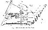 | Fig. 1 — Plan Showing Surface Layout |
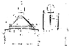 | Fig. 2 — Drawings of Sinking Doors |
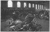 | Fig. 3 — Power House, showing Mixed-Pressure Turbo-Alternators |
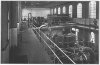 | Fig. 4 — Another view of the Power House, showing Air-Compressing Plant in Basement |
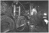 | Fig. 5 — Half-Battery of Four Lancashire Boilers serving Present Needs |
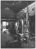 | Fig. 6 — Feed Pumps |
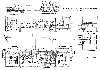 | Fig. 7 — Drawings of Power House, showing Arrangement of Winders |
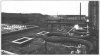 | Fig. 8 — Spray Ponds and Steam Mains, illustrating Expansion Bends |
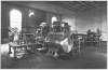 | Fig. 9 — The East Pit Winding Engine |
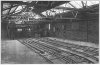 | Fig. 10 — Pit Top, Charging Side, showing Decking Plant in Course of Erection |
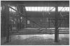 | Fig. 11 — Another View of Pit Top, showing Controls for Decking Equipment |
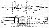 | Fig. 12 — Drawings illustrating Electro-Pneumatic Decking Plant |
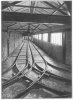 | Fig. 13 — Gantry carrying Full-way Loads to Screen House |
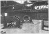 | Fig. 14 — Tipplers in Course of Construction |
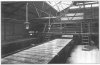 | Fig. 15 — Portion of Screen House, showing Picking Belts |
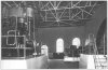 | Fig. 16 — Alternative Steam and Electric Drives for Duplicate Fans |
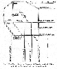 | Fig. 17 — Plan showing Layout of Roads in Shaft Pillar and Main Workings to South and East |
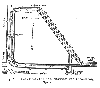 | Fig. 18 — East Shaft Sidings, showing Tub Circulating System |
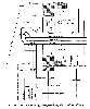 | Fig. 19 — Plan showing Proposed System of Working |
Article reproduced from a copy of the magazine held at National Mining Museum Scotland, Newtongrange, Midlothian.




 Contains public sector information licensed under the

