


 |

|

|

|
|
 |
 |
|||

November, 1928
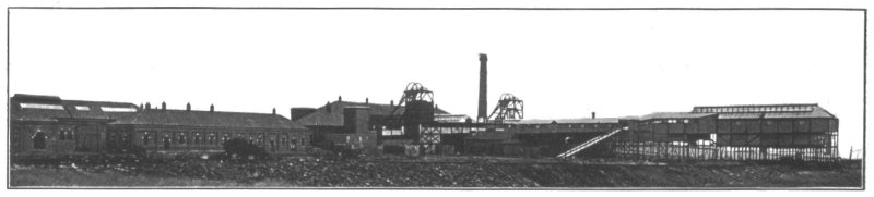
THE MORRISON BUSTY PITS
Two New Shafts have been sunk at Annfield Plain by the Holmside & South Moor Collieries Limited.
In many areas of the Durham Coalfield where coal has been worked almost from the time that collieries first existed, the shallower lying and more easily won seams are now practically exhausted, and the bulk of the output has to be obtained from the deeper and less tractable beds. In all too many instances — for the method suggests mere expediency rather than sound engineering practice — the lower seams have been worked from cross-measure drifts connected with the old, and generally narrow, shafts which have been sunk to the upper seams, but this half-hearted policy has not found favour with the Holmside & South Moor Collieries Limited, who have gone in for a hold scheme involving the sinking of two full-sized shafts, together with the erection of a modern centralised power station to serve the greater part of their colliery group. Before proceeding with our short description, we have pleasure in acknowledging our indebtedness to Mr. T. Y. Greener, the agent to the company, in affording us facilities to visit the colliery and to take photographs, while our thanks are further due to Mr. J. G. Browell, the manager, for supplying us with much of the data incorporated in the article ; also we are grateful to Messrs. W. C. & K. A. Mountain, Consulting Electrical and Mechanical Engineers, in accordance with whose specifications much of the work has been carried out, for checking our proofs and supplying certain of the drawings.
The Shafts.
Until the new pits were sunk, the company were operating the Shield Row, Three-Quarter, Main, Maudlin, Low Main and Hutton seams from the Shield Row Drift, the Morrison Old Pit, and the Louisa, Hedley and William Pits. The new shafts will serve practically the same royalty area as that covered by these collieries and will operate the various seams below the Hutton, i.e., the Towneley, Top and Bottom Busty, and Brockwell seams. Both pits have been sunk to the bottom-most seam, the Brockwell, which was reached at a depth of 130 fathoms. Each shaft has a finished diameter of 22 ft., the lining in both cases consisting of 9 in. of brickwork filled in at the back with 9 in. of solid concrete. Cast-iron boxes are built into the walling at intervals of 6 ft. to carry the buntons which support the rail guides, two of which are provided for each cage. Insets have been formed at the Towneley, Busty and Brockwell seams; in the East or downcast shaft, the main "hanging-on" is at the Busty seam and from it both the Busty and Towneley coals will be drawn, the latter being brought down to the Busty shaft siding by a cross-measure incline. The Brockwell coals only will be drawn from the West Pit.
Sinking operations were begun in June, 1923, and were finished about the end of 1925, Mr. J. Denham, of Bishop Auckland, having been entrusted with the contract. As no special difficulties were encountered the operations leave little to record, but it may be of interest to touch upon some of the main items of equipment that were assembled. Most of this equipment has now, of course, been dismantled. Temporary headgears of pitch pine were erected and stood about 56 ft. high. The main and back legs were 14 in. sq. and were fitted with cast-iron shoes at the base arranged for bolting to concrete foundations. Three cast-iron pulleys were provided, one, for winding, being 10 ft. in diameter and the other two, for the cradle ropes, 6 ft. Each headgear was equipped with the necessary tilting doors and spouts which, as shown in Fig. 2 were of somewhat unusual design. They were steam-operated, and arranged so that the discharge could be delivered direct and at either side, thus preventing any possibility of congestion with the debris trucks. R. Wilson & Sons, of Bishop Auckland, supplied this equipment.
At the East Pit the sinking engine had cylinders of 20 in. in diameter by a 3-ft. stroke, the drum being 10 ft. in diameter, and at the West Pit the cylinder measurements were 18 in. in diameter by 4-ft. stroke, the winding drum in this instance being 8 ft. in diameter. Both were fitted with Thornewill & Warham overwind prevention gear and were operated at 90-lb. steam pressure. The winches for raising and lowering the cradle were placed immediately in front and consisted of twin cylinder engines (6 in. diam. by 9 in. stroke) coupled through gearing to an 18-in, drum. Locked coil ropes 1 1/16 in. in diameter, to suit a load of 4 tons with a factor of safety of 10, and fitted with Ormerod's detaching hooks, served for winding the kibbles, while the cradle ropes, which also acted as guides for the rider, were 1 in. in diameter. The cradles themselves followed much the usual design and were built up of mild steel channels, angles and tees, with a substantial timber cleading on the top.
Compressed air was supplied by two two-stage Ingersoll compressors, one being steam and the other electrically driven. In the steam unit the high-pressure air cylinder was 12 in. in diameter and the low-pressure 17½ in., both the steam cylinders being 12 in. in diameter by a 11-in. stroke. A 150-H.P. motor was coupled to the second compressor, the diameters of the cylinders of which were 11¼ in. and 18¼ in., and the stroke 14 in. A working pressure of 70 lb. per sq. in. was maintained.
Ventilation was provided by two Sirocco single-inlet fans, one for each pit, 51 in. in diameter, and driven at 327 r.p.m. by 20-H.P. motors. At the West Pit the fan was arranged as a blower and at the East as an exhauster. The two fans, which were second-hand, had previously been used as auxiliary suction fans. The East Pit fan was installed first as a suction fan, the idea being that the shot fumes would be drawn up the ventilating tubes and thus clear the shaft more quickly; which, in fact, was the case. The objection to this system was that to ventilate the pit bottom well, the ventilating tubes had to be kept well down and so often got damaged by shots.
Having gained this experience, the West Pit fan was converted to blow before being erected, and this improved the ventilation and saved damage to ventilating tubes, but possibly did not clear the shot fumes so quickly. The blower was the most satisfactory, taken all round.
Permanent Power Plant.
A good deal of the permanent equipment was installed as the sinking proceeded, and the whole plant is now practically complete. The power house and winding engine houses form a single block of buildings, as will be gathered from Fig. 7. In effect, this block is a single building, with the winding engines at either end screened off by partitions. The portion housing the power plant is 121 ft. long by 46 ft. 6 in., and each of the winding engine compartments is 46 ft. 6 in. by 46 ft. 9 in. In common with the other buildings of the colliery the power house is a handsome structure with panelled brick walls and a slated roof, the latter being supported on steel roof principles. A 10-ton capacity travelling crane runs along the entire length of the building.
The use of steam for the winding engines has its natural corollary in the use of mixed-pressure turbines for electrical generation. Consequently, two mixed-pressure turbine sets by Belliss & Morcom have been installed, each mounted upon a combination bedplate with and direct coupled to a 1,000-kW. alternator. The electrical portion of the plant was manufactured by the Lancashire Dynamo & Motor Company and combines a direct-driven exciter and a field regulating equipment. Both sets have a speed of 2,400 r.p.m., and generate 3-phase, 40-cycle current at 2,750-3,000 volts. Multi-kinetic jet condensers of the standard type supplied by the turbine makers are provided and operate in conjunction with motor-driven rotary extraction pumps and two-stage steam-jet air-extraction pumps.
Lighting current is supplied at 220 volts by a 75-kW. motor generator of British Thomson-Houston manufacture, with a Belliss and B.T.H. steam-driven set, of the same output, to serve as standby in case of a failure in the main electrical supply.
Three 3,000 to 6,000-volt 500 kVA. capacity transformers by Metropolitan-Vickers Limited are in service, these being connected through a ring main to two smaller power stations and six sub-stations which serve other pits owned by the company. The only electrical power used underground will be the shaft bottom haulages, pumps, creepers, &c., compressed air, of course, being used in the workings.
Ample provision has been made in the power house for future extension as will be evident by reference to the general arrangement drawings in Fig. 7. Also space is provided for three large air-compressing units, one having already been installed to meet present requirements. This is a Belliss two-stage, steam-driven machine of 4,000 cub. ft. per minute capacity, delivering air at 80 lb. per sq. in. It has a speed of 250 r.p.m. and operates on a steam pressure of 120 lb. per sq. in. A view of this unit is to be seen in the foreground of Fig. 4.
The mixed-pressure sets obtain their supply of low-pressure steam from two receivers at the back of the power house. These not only deal with the exhausts from the compressors, winding engines, fan and lighting set engines at Morrison Busty Pits, but also absorb the supply from a similar range of equipment at the Old Morrison Pits which are situated about 200 yards away. This feeder is brought to the colliery in an 18-in, main. Both receivers are 30 ft. long by 9 ft. 3 in. in diameter and were manufactured by the Farrow Boiler Works Limited. Oil extractors are inserted in the mains between the receivers and the turbines.
A cooling pond 200 ft. long by 110 ft. wide and 11 ft. deep has been built for the circulating water and is arranged in four compartments, any two of which are large enough to deal with a 1,000-kW. turbine, while the whole will be large enough for three turbines. A labyrinth of piping provided with spraying nozzles is superimposed on the pond, each compartment having a complement of 70 nozzles, making 280 in all. The pressure head of water at the nozzles is 15 ft. and 16½ ft. at the inlet pipe. This equipment is capable of cooling 280,000 g.p.h. from 100° F. to 750° F. with the atmosphere at 60° F. and 75 per cent. humidity. It was supplied by J. H. Harrison & Son, of Middlesbrough.
Boiler Plant.
The boiler house is of brick with an iron roof, a full gauge track running the entire length of the building, in front of the boilers, to facilitate the delivery of the fuel, which is dropped to separate compartments opposite each unit. It is the intention to install a battery of eight Lancashire boilers, but present needs are met by four, and the other half of the battery will not be completed until the colliery is further developed. Of the units in service, three are by Galloways Limited and one by Spurr Inman, all being 30 ft. long by 8 ft. 6 in. in diameter and designed for a pressure of 160 lb. per sq. in. All the fittings were supplied by Hopkinson's, of Huddersfield. Superheaters are fixed at the back of each boiler to give 150° F. of superheat, this equipment having been supplied by Superheater Units of Swansea. Also a bank of Green's economisers has been erected consisting of 288 tubes, 11 ft. 6 in. in length. These are made up in the usual sections of eight tubes in width and arranged in nine groups, two safety valves and two blow-off valves being provided.
Feed water is supplied by two "Cameron" (John Cameron Limited, of Manchester) donkey pumps having 8½ in. by 5 in. diameter steam cylinders and 5 in. diameter rams, the stroke being 9 in. Five-inch suction pipes and 4½ in. deliveries are provided. One unit is sufficient to meet all requirements and the other serves as standby. A view of this plant is given in Fig. 6; also shown is the steam main, the joint of which is perhaps worthy of attention since it is enclosed by a Newalls flange cover, making a very neat job indeed. The whole of the steam ranges are of mild steel with horse-shoe expansion fittings at suitable intervals. A comprehensive view of part of the system is given in Fig. 8, which also shows a portion of the spraying ponds. The steam main on the boiler seatings is 16 in. in diameter and has smaller pipes branching off from 10 in. to 6 in. in diameter, to the various consuming units. Each line is fitted with a Hopkinson quick-discharge steam trap to deal with any water which may accumulate, and the whole of the system is supported on mild steel trestles fitted with expansion rollers.
Drawings and Photographs accompanying the article


Article reproduced from a copy of the magazine held at National Mining Museum Scotland, Newtongrange, Midlothian.




 Contains public sector information licensed under the

