


 |

|

|

| |
 |
 |
|||

July, 1927
Ashington Colliery - I
Drawings and Photographs accompanying the article
| Sample | Description |
|---|---|
 | Fig. 1 — Lay-out of Conveyor Faces in Five-Quarter Seam |
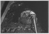 | Fig. 2 — Hopkinson Chain Cutter on Longwall Face |
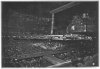 | Fig. 3 — Mavor & Coulson Arcwall Type Cutter at Work in Five-Quarter Seam |
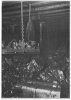 | Fig. 4 — Diamond Jigger Face Conveyor Loading into Jeffrey Conveyor |
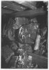 | Fig. 5 — Blackett Face Conveyor Delivering into Mothergate Conveyor |
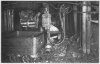 | Fig. 6 — Jeffrey Sectional Conveyor in Mothergate, Loading into Tubs |
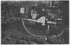 | Fig. 7 — Electrically-driven Reciprocating Coal Cutter at Work in Heading |
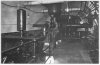 | Fig. 8 — Main Pumping Sets, each 300 g.p.m. against 600 ft. Head |
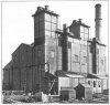 | Fig. 9 — Exterior View of New Boiler House |
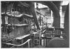 | Fig. 10 — View on Upper Grating of Boilers |
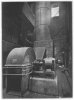 | Fig. 11 — "Sirocco" Induced Draught Fan |
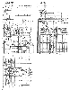 | Fig. 12 — Arrangement Drawings of Pulverised-Fuel Boiler Plant |
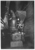 | Fig. 13 — Pulveriser and Feed Hopper |
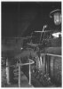 | Fig. 14 — View of Burners for one of the Boiler Units |
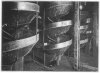 | Fig. 15 — View of the Spiral Separating Plant |
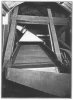 | Fig. 16 — Screen for Sizing Small Coal for Pneumatic Cleaning Plant |
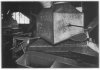 | Fig. 17 — One of the "Arms" Pneumatic Tables, showing Dust-Collecting Hoods and Delivery Chutes |
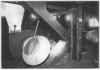 | Fig. 18— Blowing Fans for Pneumatic Cleaning Tables |
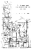 | Fig. 12 — Arrangement Drawings of Pulverised-Fuel Boiler Plant |
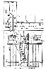 | Fig. 12 — Arrangement Drawings of Pulverised-Fuel Boiler Plant |
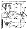 | Fig. 12 — Arrangement Drawings of Pulverised-Fuel Boiler Plant |
Article reproduced from a copy of the magazine held at National Mining Museum Scotland, Newtongrange, Midlothian.




 Contains public sector information licensed under the

