


 |

|

|

|
|
 |
 |
|||

July, 1927
ASHINGTON COLLIERY - I
Some Features of the Re-equipment Work undertaken by the Ashington Coal Co. Ltd., are briefly described and illustrated, and Details are given of a New Colliery Township being built at Lynemouth.
Ashington, one of the most familiar names in Northumberland, is associated with a group of collieries producing some three million tons of household and steam coal per annum, about half of this quantity being actually raised at the Ashington pits, with which we are immediately concerned, and the remainder at the company's Linton, Woodhorn, and Ellington collieries. In all there are six shafts at Ashington, three of which are used for coal drawing and three for ventilation and other auxiliary purposes — the Carl pit upcast shaft, for instance, being specially equipped for raising and lowering men. All the shafts are quite shallow; the Carl and Duke pits, sunk to the Low Main seam, are 180 yards in depth, whilst the Bothal pit, sunk to the Main seam, has a depth of only 72 yards. This relative shallowness of the seams has naturally led to their exploitation by means of a number of small shafts — their diameter is 13 ft. — sunk to the different beds, in preference to having two large shafts operating several onsetting levels or having long drifts between the seams.
Before proceeding we have pleasure in acknowledging the courtesy of Mr. Ridley Warham, the managing director of the company, in granting us facilities to visit the colliery, and to the various members of the colliery staff who so kindly assisted in the preparation of the data.
Mechanicalised Coal Winning.
Although Ashington may be classed as an old colliery — the first shaft was sunk in 1866 — the way in which the company has moved with the times is very well exemplified, inter alia, by the degree to which the operations at the coal face have been mechanicalised. As a typical example of this we propose to describe a district in the Five-Quarter seam, operated from the Duke pit. The seam has a section of 3 ft. 8 in., this including two dirt bands 3 and 4 in. in thickness, so disposed to leave 2 ft. of top coal, 5 in. of coal between the bands, and 8 in. of bottom coal. Both the floor and roof consist of moderately hard shale, but the seam is very much disturbed by goaf-breaks caused by previous working in the Low Main seam, 10 fathoms below. The thickness of the cover is about 500 ft., and the average gradient of the seam is 1 in 18.
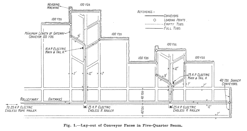
Fig. 1 illustrates diagrammatically a portion of a district and shows the disposition of the conveyors. It will be seen that the faces, which are advanced at right angles to the main cleat, are set out on the stepped longwall system and are equipped with conveyors having a standard length of 100 yards. Conveyors are also used for subsidiary transport in the mothergate, and bring the coal down to the loading points, as shown. A view of one of the mothergate conveyors — in this instance a Jeffrey sectional unit — is shown in Fig. 6, at the loading point. This is an electrically-driven machine, one of its special features being that the chain cannot lift out of the pans, which enables the conveyor to be laid over rolls or depressions in the floor without spilling the coal or loss of efficiency.
Into this conveyor the two machines illustrated in Figs. 4 and 5 deliver the coal from the right and left faces respectively ; the first of these is a Blackett machine driven by a 9-H.P. totally enclosed motor, and the second a Diamond shaker conveyor driven by a 10-H.P. motor. On the face cleared by the Blackett conveyor a Hopkinson chain cutter is in operation which makes a 4-ft. 6-in, cut in the lower dirt band, this work on the other faces being accomplished by this and various other types of longwall machines. A team of four men is employed with each cutter, the spragging being done by inserting hardwood chocks — 9 x 4 x 4 in. tapered down to 2½ in. — at intervals of 4 ft. Twelve fillers are employed on each face and average an output of 9 tons per man.
For the single faces on the right of the panel the tubs circulate through the headings and the face conveyor loads directly into the tubs. Each panel, which thus comprises 300 yards of face, is served by an electrically-driven endless rope subsidiary haulage. The rolley ways throughout are supported with steel arch girders with stay props inserted between and lagged with timber where the ground is much broken. In spite of the difficult nature of the ground, due to the workings in the Low Main seam, this system of support has been found to give excellent service and is in every way superior to the prop and baulk, or prop and girder, sets. Ordinary 3 in. x 3 in. H-section girders, cut to the required length and set with thick wood caps and sole pieces to allow for the settling of the roof, are used for the face supports.
In Fig. 7 is illustrated an electrically-driven reciprocating cutter employed in the heading between the two conveyor faces to which we have referred. Supplied by the International Channelling Company, this machine is driven by a 4-H.P. 500 volt 3-phase 50-cycle squirrel cage motor, and is set to make a 4-ft. cut in the lower dirt band. It represents one of a number of such machines employed in this class of work; in other cases various makes of reciprocating compressed-air cutters being employed.
It may be thought from the foregoing that the workings at Ashington represent a kind of conveyor and coal-cutter museum, but this diversity of plant has been purposely introduced on the experientia docet principle with a view to determining which machines give the best service in the specific conditions in which they are required to work. The latest addition to this interesting selection of machines is an Eickhoff ball frame conveyor which we should very much have liked to have seen but the fact that it was in another district some 4 miles away deterred us on the score of time. In all, 120 coal cutters of various types and 20 face conveyors — as distinct from gateway conveyors — are at present in use, 75 per cent. of the output of the colliery being obtained by undercutting.
Other Underground Equipment.
Reference has already been made to the auxiliary haulages in use for gathering the coal from the conveyor loading points. Altogether, 80 haulages are employed in bringing the coal to the shaft bottom, these for the most part being electrically driven, the motors ranging from 2 to 60 H.P. Apart from a number of "Tugger" hoists employed — which constitute the 2-H.P. units — practically the whole of these haulages are of the endless-rope type and have a speed of about 1½ mph. The roadways are laid with 24 lb. per yard rails and, in the Five-Quarter seam, are supported with flexible steel arch girders on the Tredegar system.
For use with the conveyors in the yard seam a special 25-cwt. capacity steel bodied tram has been introduced, mounted on Skefko ball-bearing wheels. The wheels have a diameter of 12 in. and are mounted in self-aligning axle boxes to reduce the friction when negotiating curves. So far 100 of the tubs, which were supplied by the Birtley Iron Company, are in commission, but there is every possibility of this number being extended as more conveyors are introduced. We may mention that we were very interested to see this development, as hitherto the large capacity tub has not found much favour in Northumberland and Durham. Probably smaller tubs are in general use in this coalfield than in any other, 9 cwt. being more or less a standard capacity and 7 cwt. being quite usual in some of the older collieries. We have so frequently pointed out the advantages of having larger capacity tubs, however, that it would be out of place to dwell upon it here. Another type of tub in use is also provided with a steel body and has a capacity of 12 cwt., the tare being 5 cwt.
The main pumping sets are illustrated in Fig. 8. These comprise two Pearn three-throw ram pumps each capable of raising 300 g.p.m. against a 600 ft. head, the rams being 9 in. in diameter and having a 12-in, stroke. They have a speed of 46 r.p.m. and are driven by 80-H.P. 500-volt 3-phase induction motors through double reduction gearing. About 64 inbye pumps are engaged in draining the workings these being driven by compressed air or electricity as expediency dictates.
Pulverised-Fuel Boiler Plant.
Colliery companies are frequently accused of clinging to old-fashioned and obsolete methods, and although this may be substantially true in many cases, there is ample evidence that in others the plant is kept well up to date, and any new means to secure better results are readily adopted. The new boiler plant at Ashington may be cited as a case in point, as it is only within very recent years that pulverised fuel firing has become established, and even now, in many quarters, is regarded as being a bold innovation. Among the primary advantages offered by the system are the high efficiency of combustion, the flexibility of control and the low-grade of fuel which can be burnt. Only about half the amount of excess air required in ordinary stokers is needed, and the finely divided state in which the coal is burnt ensures that practically all the combustible matter is usefully consumed. Tests in various plants have shown that as a general rule less than a half per cent. of unburnt carbon remains in the ash, against 1 to 1½ per cent. with mechanical stokers, and that the flue gases contain 16 per cent. and over of CO2, compared with 13 to 14 per cent. in the usual form of modern boiler plant.
The installation at Ashington consists of four Stirling water-tube boilers of 33,000 lb. evaporative capacity per hour each, with a continuous overload capacity of 40,000 lb. The working pressure is 200 lb. per square inch, the steam having a final temperature of 550° Fahr. Fig. 12 gives drawings of the plant from which our brief description will be readily followed.
The raw coal, duff from the Low Main, Five-Quarter and Main Seam, is pulverised to the required fineness in a 5-roll Raymond mill, this and the remainder of the pulverising equipment, combustion chamber, &c., having been supplied by Underfeed Stoker Co. Ltd. As soon as the coal is reduced to the proper degree of fineness it is removed by a system of air separation and stored in a bunker capable of carrying several hours' supply.
A series of feeders are situated at the bottom of the bunker, and in these the coal is mixed with a quantity of air, and then passed through pipes to the burners. The flames are projected downwards with such a velocity that the hottest zone is just a little below the centre of the combustion chamber, and these are of such length that the rising gases have ample time to complete combustion before reaching the boiler tubes. Cross currents of secondary air, introduced through ducts in the walls of the combustion chamber, not only serve to complete the combustion, but also to keep the walls cool — a function in which they are assisted by screens of water tubes, arranged along the side walls, back and bottom of the chamber. These water screens, which absorb radiant heat that would otherwise be imparted to the refractory walls, form an integral part of the boiler circuit. The main function of this screen is to create a relatively cool zone at the lower portion of the combustion chamber through which the molten ash passes and solidifies into a finely-divided state before reaching the ash hoppers. At the same time it forms an effective addition to the heating surface of the boiler. The side wall tubes add a heating surface of 157 sq. ft., for instance, and the screens at the back and the bottom of the chamber a further 110 sq. ft. ; the heating surface of the boiler itself is 5,904 sq. ft. Superheating is accomplished by a Stirling convection type unit, having a heating surface of 690 sq. ft. The combustion chamber, which is lined with Stein's "Thistle" brand refractories, has a volume of 3,000 cubic ft. Each of the two stacks is 6 ft. in diameter and 96 ft. high, the draught conditions being regulated by electrically-driven fans giving a forced draught of 2½-in. water-gauge pressure and an induced draught of 1¾ in. The Usco water-sluicing system of ash removal, developed by the Underfeed Stoker Company, is incorporated, this firm having also supplied the plate type air heaters, which have a heating surface of 3,552 sq. ft. each.
Water is obtained from the Wansbeck river, a distance of about three miles, a centrifugal pumping station at the river delivering 300 g.p.m. through a 7-in, main. A Paterson lime-soda water softener is installed, having a capacity of 1,000 g.p.h.
The plant has been in commercial operation since May 1, 1926, and proved of considerable value during the duration of the coal dispute when only the pit mound waste was available for steam-raising purposes. The Ashington Colliery Company were the first colliery company to install equipment of this character on a large scale, and their lead has been followed in many parts of the country.
Power Plant.
Electrical power generating plant comprises two high-pressure 1,000-kW. turbo-alternators by Parsons and a 1,500-kW. mixed pressure set by the Metropolitan-Vickers Electrical Co. Ltd. The two former units are provided with surface condensers and the latter with a jet installation. All these three sets have a speed of 2,400 r.p.m. and generate 3-phase 40-cycle current at 550 volts, the whole plant running in parallel with the Newcastle Electric Supply Company's system. Two 550 to 3,300-volt transformers of 500-kVA. capacity each are provided, these being connected with the supply company's 3,300 to 20,000-volt transformers for transmitting current to, or receiving it from, the high-tension lines. The main distribution and control board comprises two ironclad Reyrolle units of standard design.
Compressed air is generated in a Brown Boveri turbo unit driven by a Metropolitan-Vickers turbine rated at 1,020 B.H.P., the capacity being 6,000 cub. ft. of free air raised to 60 lb. per square inch. This set is provided with a jet condenser and delivers the air into a 30 ft. by 7 ft. 6 in. receiver, from which it is conducted underground by two 10-in. diam. mains, one down the Carl upcast shaft and a second down the Bothal upcast. Further air-compressing equipment consists of a 4,000 cub. ft. capacity Walker reciprocating unit, having 20 in. by 5 ft. stroke cylinders.
The 1,500-kW. mixed pressure turbine draws its low-pressure steam from two accumulators of the Rateau type, which are fed by the Carl and Duke pit winders (each 25 in. diam. cylinder by 6 ft. stroke), two surface haulage engines (16 in. by 2 ft. stroke cylinders), the Bothal pit winder (20 in. by 4 ft. stroke cylinders) and the Walker reciprocating compressor just mentioned.
Two cooling towers are provided, that for the turbo compressor having a circulating capacity of 110,000 g.p.m., whilst the power station cooler is capable of dealing with 200,000 g.p.m.
Screening and Cleaning Plant.
Two quite distinct sets of screens are installed, those for the Bothal and Carl pits comprising three main jigging screens and, three small screens for the nut sizes. These operate in conjunction with three steel plate picking belts, which deliver the best quality coals direct to the railway wagons. The large coal, i.e., above 3½ in., from the Yard seam, forms a special household variety and is loaded separately from one belt, while the two remaining belts handle the other high quality coals from the 7/8-in. size upwards. The remaining qualities are cleaned on the battery of spiral separators shown in Fig. 15. This equipment, which was supplied by Hugh Wood & Co. Ltd., deals with three sizes of material cobbles (3½ to 2½ in.), trebles (2½ in to 1 in.), and doubles (about 7/8 in.). All below 7/8 in. is treated on a pneumatic screening plant to which we shall return later.
The screening plant for the Duke pit similarly comprises three sets of jigging screens and three steel plate picking belts provided with lowering jibs. One of these units, it is interesting to note, has been provided throughout — jiggers and belt — with ball bearings; this conversion was undertaken by the Blantyre Engineering Company, and the unit has given very satisfactory service indeed. It has now been running two years. At the time of this conversion the coal tipplers were renewed by the same firm, three automatic units being installed.
Pneumatic Cleaning Plant.
The special feature of the screening and cleaning plant consists of the new air tables which have been put to work. This equipment is capable of dealing with 30 tons per hour of the small coal passing through the 7/8-in. mesh plates of the main screening units. Two tables are provided these being of the "Arms" type marketed by Hugh Wood & Co. Ltd., who supplied the plant as a whole. The large table, shown in the foreground of Fig. 17 takes the coal above 3/8-in. mesh, whilst the other handles the material from 3/8-in to 3/16 in. No attempt is made to clear the duff coal below this, which is consumed without further treatment in the new pulverised-fuel boiler plant.
The building in which the plant is erected was originally designed for a rotary duff screen, so that the present plant has not been arranged as it otherwise would have been had it had an entirely new housing. Small coal is brought in railway wagons and deposited in a ground bunker, from which it is raised by means of a canvas band of bucket elevator, to the "Arms" screen illustrated in Fig. 16. This screen, which is constructed of wire mesh and is set almost horizontal, is operated by ball-bearing eccentrics fitted in the screen head, the delivery end being hung by flexible hangers. It is claimed that the arrangement of the eccentric drive — which gives 500 oscillations per minute — and the specially located hangers lift the material clear of the mesh at every stroke, and thus affords very accurate sizing. Other qualities claimed for the screens are the large capacity per unit of floor space, the low head room required, and the low power consumption — 2½ H.P. being all that is necessary in the present case. From the screens, the two sizes of coal are fed direct to the tables. The pea table, which is fully loaded, deals with from 8 to 10 tons per hour, but the nut table is not working to the best advantage. Normally, it is capable of cleaning 15-20 tons per hour, but as 40 per cent. of the raw material consists of duff below 3/16 in., this table is not loaded to its full capacity and its potential output is not obtained. With a permanent plant, of course, it would be easy enough to balance matters so that each unit would be worked to full capacity, but it has naturally been impossible to secure such favourable conditions in an existing building and elevator intended for other purposes.
The middlings are discharged to the bottom strand of a scraper conveyor and returned to the tables for re-treatment, the top strand of the conveyor carrying the stone in the opposite direction along a gantry outside the building and discharging it into a hopper. Auxiliary equipment comprises the Sturtevant blowing fans illustrated in Fig. 18, which also shows the butterfly valve for the inlet control, this being operated from the table floor above. The fan for the larger table is belt driven at 715 r.p.m., requiring 15 H.P., and is capable of delivering 11,800 cubic ft. of air against a 4-in. w.g.; that for the small table has a speed of 550 r.p.m., and has a capacity of 8,000 cubic ft. per min. against a 2½-in. w.g., the power required in this case being 6 H.P. It will be noticed that adequate provision has been made for the removal of the dust and it is noteworthy that the precincts are remarkably free from this nuisance. The exhauster fan which operates this adjunct of the plant has a capacity of 22,000 cubic ft. per min. against a 11-in. w.g., and absorbs 18 H.P.
In view of the somewhat restricted application of pneumatic cleaning in the above instance it is perhaps only fair to add that the system has been successfully used in America with coal passing 2-in square mesh (though on coal above 1 in. the power consumption is high), and also on coal for a 1/8-in, to 60 mesh. Accurate sizing of the raw coal is absolutely essential to successful results, as the settling ratio of coal and refuse in air is about 1 to 2.
Drawings and Photographs accompanying the article


Article reproduced from a copy of the magazine held at National Mining Museum Scotland, Newtongrange, Midlothian.




 Contains public sector information licensed under the

