


 |

|

|

| |
 |
 |
|||
June, 1925
A Durham Sinking
Drawings and Photographs accompanying the article
| Sample | Description |
|---|---|
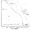 | Fig. 1 — Sketch Map showing Relative Position of New Sinkings |
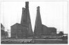 | Fig. 2 — General View of the Boring Derricks |
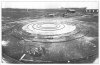 | Fig. 3 — Covered Fore Shaft, No. 1 Pit |
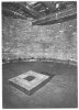 | Fig. 4 — Inner Chamber of the Fore Shaft, showing Central Bore-hole for use in Freezing Operations, and sump for the return of Boring Water |
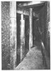 | Fig. 5 — View showing Outer Chamber of Fore Shaft |
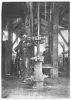 | Fig. 6 — Boring in Progress |
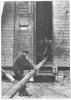 | Fig. 7 — One of the Freezing Tubes being put into Position for Lowering |
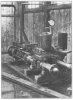 | Fig. 8 — One of the Pumps supplying Boring Water |
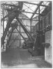 | Fig. 9 — Boiler Plant for Present Requirements |
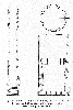 | Fig. 10 — Details of Boring Road and of the Crown and Core Extractor used in the Prospecting Bore-Hole |
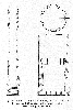 | Fig. 11 — Details of Boring Road and of the Crown and Core Extractor used in the Prospecting Bore-Hole |
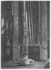 | Fig. 12 — Chisel Resting on Top of the Guide Pipe |
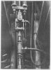 | Fig. 13 — Hose Connection to Bore Rods, and Part of the Suspension Gear |
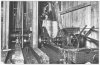 | Fig. 14 — The Reciprocating and Hoisting Equipment: the Clutch and Band Brake are also shown |
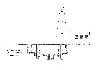 | Fig. 15 — Sectional Elevation through Fore Shaft |
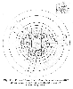 | Fig. 16 — Plan of Fore Shaft Top, showing the position of the Derrick and the Concentric Rails on which they slide |
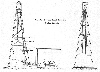 | Fig. 17 — Side and Front Elevation of Boring Derrick |
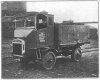 | Fig. 18 — Pagefield Lorry |
Article reproduced from a copy of the magazine held at National Mining Museum Scotland, Newtongrange, Midlothian.




 Contains public sector information licensed under the

