


 |

|

|

|
|
 |
 |
|||
| Colliery Engineering | February, 1925 |
Power Plant.
At present, current for the motors is obtained from the Newcastle-upon-Tyne Electric Supply Co. Ltd., but a 1,000-kw. mixed-pressure turbo-alternator by the English Electric Co. Ltd. will shortly be installed. At the time of our visit the foundations for this unit were in the course of erection. Exhaust steam from the winding engine, a surface hauling engine, the compressor, feed pumps. &c., will be utilised, and this will be stored in an accumulator to afford regularity of supply. Provision is, of course, made for the high-pressure steam from the boilers to be admitted automatically in case of necessity. Sufficient electrical energy will be generated for various underground haulage sets, which will be mentioned later.
The air compressor, which was installed six months ago, is a horizontal steam-driven unit by Walker Brothers (Wigan) Ltd. It has a capacity of 5,000 cub. ft. of free air per minute to 80 lb. pressure, with a steam pressure of 110/120 lb. per square inch. The steam cylinders. 27 in. and 43 in. in diameter, are compounded and the air is compressed in two stages in cylinders 41 in. and 26 in. in diameter by a 4-ft. stroke. Valve gear on the steam cylinders is of the Corliss type, and a speed governor acts in conjunction with an air-regulating apparatus, controlling the expansion of steam in the high-pressure cylinder, through the medium of trip gear.
Both air cylinders have circular water jackets, completely encircling the cylinder barrel, and are equipped with light disc valves. These afford a large area for the free passage of the air through, as well as round, the valve, thus rendering a low lift sufficient, with consequent high efficiency and quiet working when running at high speeds. The clearance of the air cylinders is very small, so that practically the whole of the compressed air is expelled. An inter-cooler is provided, constructed of mild-steel plates, having a large cooling surface of brass tubes for the water circulation.
Some Underground Features.
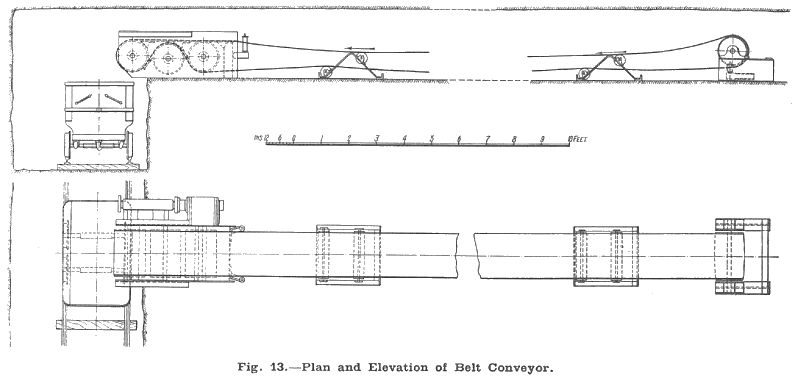
Underground haulage, in the main, is effected in two stages, but in some cases, where cross measure drifts have to be negotiated, the output is handled by three separate haulages. The coal from the Tilley seam, where very progressive working methods have been adopted, is brought to the shaft by the electrically driven main-and-tail haulage set illustrated in Fig. 8; the motor is a 200-h.p. 440-volt 40-cycle induction machine, fitted with liquid starter and control. It is from the works of the English Electric Co. Ltd., the gear itself being manufactured by Kilmarnock Engineering Co. Ltd. A 2-in. circumference hemp core rope is used, the tubs being run in sets of 40. The latter are of sheet steel construction, the body, which is mounted on a steel tram, being narrowed toward the bottom to accommodate the 10-in, in diameter cast-steel wheels. An illustration is given in Fig. 13, showing one of these tubs in position under the conveyor. They have a capacity of 9 cwt., a tare of 51 cwt and were manufactured by Robt. Wilson & Sons, Bishop Auckland.
Between the coal face and the main haulage landings the transit is effected, in sets of 20 tubs, by main-and-tail air-driven auxiliary units. Two sizes are in use the smaller having cylinders 4 in. by 7 in., and a speed of 318 r.p.m., and the larger having cylinders 5 in. by 8 in. and a speed of 276 r.p.m. The smaller haulage develops 20 h.p., and has a rope travel of 250 yards, the equivalent figures in the instance of the larger hauler being 26 h.p. and 300 yards. Both are designed for 80-lb. pressure and have a rope speed of 3 miles hour ; also the gearing ratio, 6 to 1, is the same in each case. Ropes for these auxiliaries are in. in diameter. These gears, which are S. A. Ward's patent, were supplied by R. H. Patterson & Co. Ltd., of Newcastle.
System of Face Working.
The mothergates are kept 40 yards in advance of the coal face, and are made 7 ft. wide ; this width being increased to 10 ft. where pass-byes are necessary. Not only does this long lead enable the whole of the empty auxiliary set (20 tubs) to be hauled past the tippler end of the conveyor, but it also leaves a considerable margin to spare (10 yards), so that if any difficulty should occur in driving the mothergate heading, the work on the longwall face is not immediately impeded. This elasticity is a very commendable feature in machine-worked faces, and amply repays any extra cost that may be incurred in driving in the harder coal, so far in advance of the working face. When too narrow a working margin is maintained endless trouble is liable to occur if for some cause or other — and there are always so many causes in pit-work — work in the heading has to be suspended for a shift or two.
When the auxiliary set is brought "in-bye" of the conveyor jib, the tubs are not disconnected but are brought under the jib one by one, as they are filled, upon the necessary signals being given to the haulage attendant by the lad operating the conveyor motor. Electrical signals are used, the cables being insulated.
In the Tilley seam, the most convenient length for a longwall face is considered to be 90 yards, but a difference of 20 yards, more or less, can easily be negotiated without any complications, should the conditions require that a longer or shorter face be desirable. In the North district the actual length of face is 102 yards; here the height of the seam is 2 ft. 6 in., and the coal, which is worked "end" on, or "headways" course, is undercut by a Sullivan chain machine. This machine, which has a reversible jib, appears to be doing excellent service in these conditions and is very well spoken of by the management. The hard floor of the seam necessitates the cut, 4½ in high by 4ft. 6in. deep, to be made in the coal; this cut is at floor level. Shot holes are placed at 6-ft. intervals.
All timber is set by a face timberer, who is solely occupied in doing this work. A maximum distance of 4 ft. 6 in. is specified between the face and the first row of props, between each row of props and between adjacent props in the same row. Planks 5 ft. in length, supported by two props, are placed at right angles to the face. Hardwood chocks, 2 ft. sq., are placed between the conveyor and the goaf at 4-yard intervals. Care is taken to maintain the longitudinal rows of props in a perfectly straight line, and as the planks, which are 3 in. in thickness, overlap to some extent, the system gives an impression of great security. The necessary timber is brought up the back gate or timberway (which also serves as a second exit for the men), the transport along the face being effected by a Meco belt conveyor. A drawing of this conveyor is given in Fig. 13, which shows all the essential details. The woven cotton belt, 20 in. wide, has a capacity of from 5 to 20 tons per hour. It is driven by compressed air turbine situated at the discharge end. No clutch is necessary, the throttle affording an admirable control. The manner in which the tension is applied, and in which the machine is anchored, will be readily understood from the drawing. Anchorage for the roller frames is not necessary; they are simply placed in their proper position on the floor of the seam and remain there. The belt and rollers are perfectly flat, and it might appear that much of the coal would scatter off the sides, due to the vibration, but this is not the case. The men soon become adept in placing the coal on the belt, and the motion seems to have very little effect on it even when (as often happens) it is piled up to the natural angle of repose ; the surprisingly small quantity that does fall off, or is scattered in the casting, is easily cleaned up from time to time.
This machine has proved most satisfactory in meeting the conditions at the colliery, and has practically worked without giving any trouble since introduced in 1916; it is interesting to note that several important improvements in the original design have been innovated as a result of the experience gained at this colliery. Chief among these is the design of roller standards and the dividing of the conveying belt into 20-yard lengths, both improvements being calculated to facilitate the flitting operations. Formerly the roller supports consisted of a frame arrangement which had to be erected and fixed with splits of wood between the floor and roof. Much time was thus taken in erecting and taking down the supports; also correct alignment was a matter which required somewhat elaborate care. The present roller frames can be moved forward in a second or two, and further adjustment to bring them into correct alignment is a trifling matter when the tightened belt indicates the position in which they should be. These are now standard equipment by the Mining Engineering Co. Ltd.
When the 20-yard lengths of belt are rolled from the ends towards the centre they form conveniently-sized bundles (3 ft. by 18 in. by 20 in.) which can be easily handled by the flitters. The connections, which consist of a metal hinge fastening, are quickly fastened and unfastened by the insertion or removal of a mild steel pin. Longer lengths of belting — originally the belt was supplied in lengths of from 60 to 100 yards — were found to be much too cumbersome to handle in the height available.
Five "flitters" are required to move the conveyor forward and to draw all back timber and chocks. The tension end is first slackened, and the belt is split up in 20-yard lengths. These are rolled from the ends towards the centre and are manhandled forward into the new position. Roller stands are placed about 3 yards apart, the engine is moved up the exact distances of the undercut, and the belt so placed that a minimum distance of 2 ft. from the coal is preserved. Ten men constitute a filling shift, two shifts being required to clear the face. Average flitting time for the conveyor is from 2½ to 3 hours.
Shaker conveyors, also by the Mining Engineering Co. Ltd., are in use on one other face, but the general consensus of opinion among both officials and workmen is unquestionably in favour of the belt machine, in the peculiar conditions obtaining in this seam.
Apologia.
It will be seen that the management of Pelton Colliery take an active interest in the latest improved methods and are ready to introduce them wherever practicable. both underground and at the surface. At the time of our visit no actual tests had been conducted on the boiler plant, so that it has been impossible to include adequate figures demonstrating the results of the powdered fuel firing. So far only the No. 1 boiler has been fired by powdered fuel, using punching machine cuttings. The result is excellent, steam pressure being fully maintained throughout the 24 hours. A rough test of evaporation was made, and it worked out at 8 lb. of water to 1 lb. of fuel.
Careful tests will, of course, be made later, and by the courtesy of the officials to whom we have already alluded, we expect shortly to be able to give some account of them. In the editorial columns of our December issue we drew attention to the value of information of this kind, and we are glad to give ad hoc a specific instance of the generous pooling of the fruits of individual experience.
Drawings and Photographs accompanying the article


Article reproduced from a copy of the magazine held at National Mining Museum Scotland, Newtongrange, Midlothian.




 Contains public sector information licensed under the

