


 |

|

|

|
|
 |
 |
|||

February, 1925
RE-EQUIPMENT IN DURHAM
We describe and illustrate some Features of Pelton Colliery, Pelton Fell, Co. Durham, Special Reference being made to the Boiler Plant and System of Longwall Working.
The extensive adoption of powdered fuel firing in America, and to some extent — by important industrial concerns — in this country, affords ample evidence of the commercial soundness of the scheme. To the collieries the system would appear to have special attractions, particularly where quantities of unmarketable slack are necessarily brought to the surface and tipped over the waste heaps, or cast into the goaf. In many cases some form of patent firegrate will successfully meet the conditions, but in others the use of these appliances is attended by only a moderate degree of success. Powdered fuel firing has thus given a new impetus to the utilisation of material of this kind, and we have awaited with considerable interest its adoption by a colliery company. We are pleased, therefore, to give some account of what we believe to be one of the first powdered fuel plants installed at a colliery in this country. An account of this kind, to be of value to our readers, cannot be written without the ready co-operation of the higher officials of the colliery and in this connection we gratefully acknowledge our indebtedness for the facilities which were afforded us by the general manager, Sir Robert S. Gardiner, and the kind assistance given us by Mr. Guy E. Armstrong, the manager, in supplying many of the details.
The Original Boiler Plant.
The plant consists of five boilers of the Woodeson type, two having an evaporative capacity of 15,000 lb. of water per hour each, and the remaining three a capacity of 8,000 lb. per hour each. Each boiler comprises four 4-ft. drums connected, so far as the vertical drums are concerned, by perfectly straight tubes. The two top drums have steam and water interconnections, and suitable connecting tubes are provided to the bottom water drums. To all intents and purposes the drums, top and bottom, are of circular section, but they have flat parts pressed out hydraulically to facilitate the use of straight tubes. The top drums also have a series of manhole doors along the side opposite the tube plates, so that any tube can be conveniently withdrawn without having to cut it or otherwise make awkward manoeuvres.
The boiler is suspended from steel girder work, and the lower two drums are perfectly free to take up their own position due to expansion or contraction except that a tie rod is provided on the front bottom drum in order to take any tilting stress off of the pipework connections. Each bottom drum is provided with a blow-off connection, and there is the usual blow-off isolating valve. This arrangement of connecting tubes between bottom drums is such as to facilitate the precipitation of mud in the back drum, which is, of course, the coolest, and from which the sediment can be expelled through the blow-off.
The baffling of the boiler is of a simple nature, as can be seen, and a sufficiency of handholes and inspection doors has been provided so that access is easy to every external part of the boiler. The water gauge is connected to the front top drum, in which is arranged the usual high and low water alarm floats and whistle. The safety valve is mounted on the top back drum.
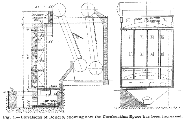
As will have been gathered from the design and the name previously mentioned, all five of the boilers were supplied by Clarke Chapman & Co. Ltd., of Gateshead. Although perhaps rather small units, they have given very reliable service. Originally these units were fitted for gas firing, the gas being obtained from a battery of beehive coke ovens. The use of these ovens was discontinued in March, 1923, however, and since that time the boilers have been handfired, a system for which, as will be seen in Fig. 1, they were alternatively fitted. Until six months ago the working pressure was only 80 lb. per square inch, but since then it has been increased to 120 lb. to meet the requirements of new additions to the surface plant.
The feed pump ("Woodeson's" patent) was also supplied by Clarke Chapman & Co. It is a vertical single-cylinder double-acting pump, the stroke being 26 in. and the diameters of the steam and water cylinders being 14 in. and 10½ in. respectively. Eight double strokes are given per minute, the capacity of the pump being 70,000 lb. of water per hour. Injectors by Holden & Brooke Limited are also fitted, two being provided for each of the boilers. No. 12's, having a capacity of 2,861 gallons per hour, are fitted to the larger units, and No. 9's, having 1,610 gallons per hour capacity, are fitted to the smaller.
The two 15,000 lb. evaporative capacity boilers are provided with Crosthwaite furnaces, but ordinary firebars are fitted in the three smaller units.
With the hand-firing arrangements nine firemen are employed — three in the morning and afternoon shifts, and three in the night shift. In addition, an ash wheeler and a boiler-minder chargeman are employed in each of the three shifts, making a total of 14 shifts worked during the 24 hours. The use of powdered fuel will enable seven of these shifts to be dispensed with, the personnel being reduced to a boiler minder, a pulveriser attendant per shift, and an ash remover for the shift, thus making a total of seven shifts per 24 hours.
With the hand firing, using best unscreened coal (calorific value, 12,000 B.Th.U.), the average amount of water evaporated per pound of fuel is 6½ lb. about 380 tons per fortnight are used. The Powdered Fuel Plant Co. Ltd. are consultants for the conversion work, which is being carried out by Clarke Chapman & Co. Ltd. ; a guarantee has been given that at least 8 lb. will be evaporated with powdered fuel containing as much as 20 per cent. of ash, so long as calorific value is not under 10,500 B.Th.U.
Economies of the New Plant.
In view of the above comparisons little more need be said to emphasise the economies effected. It must be remembered, however, that the fuel used in the new plant has hitherto either been thrown into the goaf, or that portion which was necessarily brought to the surface, tipped over the waste heaps. It consists entirely of cuttings from the machine faces in the Tilley and Townley seams, the former predominating. Very little extra labour and cost is entailed in bringing the cuttings to the surface and, moreover the alterations and additions which have been made to the boiler plant have been conducted without causing any stoppage, nor have they been prohibitively expensive.
The cuttings are separately filled into tubs before the coal is shot down Belt conveyors have been found to handle the material most successfully at the face on shaker conveyors it is apt to pack into a cement-like layer in the bottom of the troughing, and there it lodges even though the rougher material rides over it. In the tubs it again packs, due to the shaking it receives in transit, into a hard mass which can only with difficulty be penetrated by a shovel. This is a fact of some consequence, since it prevents considerable quantities of it being blown off the top of the tubs — as might be conceived — and deposited on the haulage planes.
Additions and Alterations to Boiler Plant.
At the surface the cuttings are tipped into the special hopper illustrated in Fig. 3. They are arranged to fall on an ordinary bar screen; the material above 1½ in. automatically drops into a lorry to be used for workmen's coals. Stuff falling through the screen is conducted to the boiler house by an ordinary scraper conveyor 100 ft. in length and having a capacity of 10 tons per hour, driven by a 4-h.p. motor. It is there delivered to a second conveyor, operated by a 3-h.p. motor, traversing the feed hoppers, which can be fed proportionately by adjusting the slides covering the hopper openings. The adjustment is effected by means of a screw and wheel, the arrangement being very similar to an ordinary gate valve. The shape and overall dimensions of these storage bins may be gathered from the plan and elevation in Fig. 2. They are composed of sheet iron, strengthened where necessary by angles. It will be seen that the design has been modified to suit the two sizes of boilers. The purpose of the storage bins is, of course, to give the necessary elasticity between the supply and demand ; the larger hoppers have a capacity of 20 tons, and the smaller 15 tons, or enough to last for 24 hours' full firing.
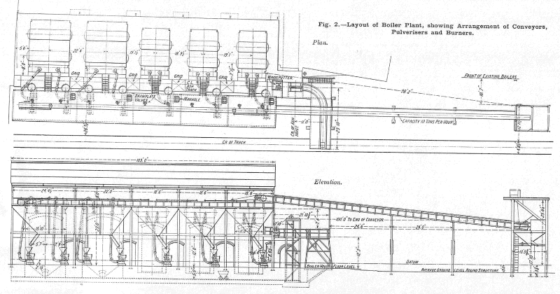
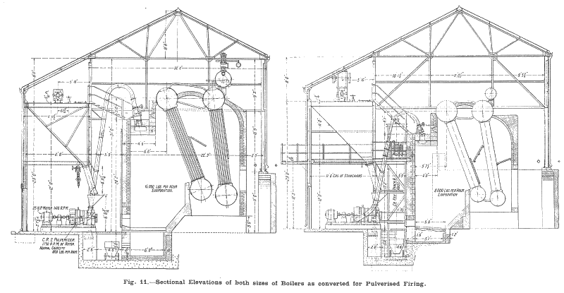
The fuel is fed down to the pulverisers by a 12-in. square sheet-iron chute. The feed automatically stops by choking itself when the small hopper, to be seen on top of the pulveriser, is full. Alternatively, the feed can be stopped by man-handling a lever which brings a hood arrangement over the chute exit. The pulverisers are of the revolving rigid-hammer type, the axle on which the six manganese steel, flat-faced hammers are mounted being rotated at 1,750 revs, per mm. Their capacity is 1,400 lb. of coal per hour each. Unfortunately, due to the fact that the supply current has a periodicity of 40, it has been impossible to arrange a direct drive for the pulveriser motors. These are 25-h.p., 440-volt, three-phase, open-ventilated machines and have a speed of 1,170 r.p.m. ; gearing has thus been introduced to give the pulverisers the requisite 1,750 r.p.m. On an average, about 100 kw. per hour, representing about 4 per cent. of the boiler capacity, are consumed by the pulveriser and conveyor motors. Each of the seven pulveriser motors consumes 14 kw., making a total of 98 kw., and the conveying motors require about 6 kw. for eight hours a day, making the average consumption 2 kw. per hour. A centrifugal fan is mounted on the same shaft as the hammers, to create the draught necessary to propel the powdered fuel through the 6-in. galvanised pipe to the combustion chamber. The path of this pipe will be seen and the point at which it enters the combustion chamber will be gathered from Fig. 12.
No essential alterations have been made to the boilers themselves, but it will be seen from Figs. 1 and 9 that the combustion chambers have been considerably enlarged. The capacity of the chambers has been increased by 533 cubic ft. in the case of the 8,000-lb. units and 1,040 cubic ft. in the two larger (15,000-lb.) units. It will be seen from the plans and elevations, to which reference has already been made, that the brickwork extensions have been strengthened by channel girders. The sides are completely encased by iron plates which are bolted to the side girders.
Removal of the ash is effected through a tunnel immediately in front of the boilers, as will he seen in Fig. 2. The tunnel accommodates a 10-cwt. capacity pit tub, which is hoisted in the manner shown in Fig. 13, to enable the ash to be tipped into a wagon The hoisting gear consists of a double-drum winch, operated by 5 by 8 in. twin cylinders, worked with steam from the boilers.
Water softening presents somewhat unusual difficulties, and a new Lassen-Hjort plant, by the United Water Softeners Limited, has just been put down to provide (3,000 gallons per hour. The water is obtained from a stream which is intermittently polluted by an influx of pit water. In order to secure uniformity of supply, two reservoirs have been built, each capable of providing sufficient water to the boilers for 24 hours. Analysis is taken every morning before the reservoir which is to provide the day's supply is tapped, and the lime and soda can thus be accurately proportioned.
Drawings and Photographs accompanying the article


Article reproduced from a copy of the magazine held at National Mining Museum Scotland, Newtongrange, Midlothian.




 Contains public sector information licensed under the

